

How to Position Ship Launching Airbags Under the Vessel: 2026 Step-by-Step Guide
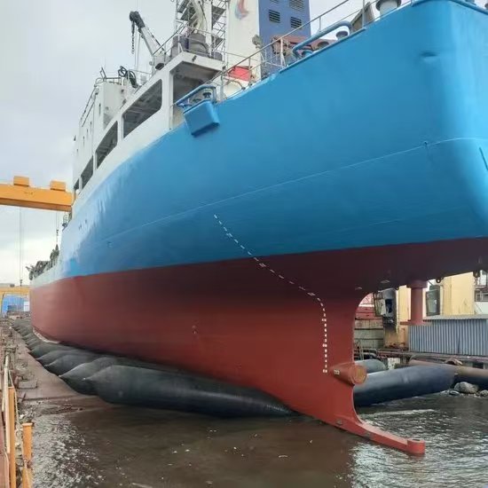
How to position the ship launching airbags
Last updated: 28 October 2026 · Reading time: 11 min · Author: [Jack], Marine Launching Engineer, 14 years on the slipway · Reviewed against: GB/T 41888-2022 Ship and marine technology — Airbag launching procedure for ships
If you searched this phrase, you probably already know the number one mistake in an airbag launch: bad bag arrangement, not bad bags. Industry incident reviews repeatedly find that more than 80% of accidents trace back to inappropriate airbag arrangement and poor launch-site conditions, not product failure. Positioning is where a launch is won or lost. This guide walks through the full calculation and on-site routine, with real numbers from an actual 3,655 t barge launch.
What this guide covers
- Pre-positioning checks (skip these and the numbers below are worthless)
- How many bags you need — the calculation
- Spacing rules — maximum and minimum centre-to-centre distance
- Layout patterns: single-row, crossover, two-row
- The physical placement routine on the slipway
- Inflation, load transfer, and levelling
- Common mistakes that cause hull sag or bag puncture
- FAQ and downloadable checklist
Step 1 — Pre-positioning checks
Before a single bag touches the hull, verify five things.
1. The ground. The launch track must be clean, level, and free of nails, weld beads, rebar ends, and stones. For concrete or gravel, lay steel plates or chafing strips. Side-to-side level tolerance should not exceed 80 mm, and ground bearing capacity must be at least twice the airbag working pressure. A single rebar stub is enough to puncture a bag mid-roll.
2. Slipway slope. Airbags can work on slopes from 1:70 to 1:10, versus roughly 1:20 for greased ways. Slope is set by vessel weight, friction, and winch capacity — not by habit.
3. Bag specification. Diameter, effective length, ply count, and certified line load must be matched to the vessel. Use only bags complying with ISO 14409:2011, with an airtightness test showing ≤5% pressure loss per hour and a burst margin ≥3× working pressure. Note that the former industry standard CB/T 3837-2011 was withdrawn in December 2023; current Chinese practice references the national standard GB/T 41888-2022.
4. Bag inspection. Every bag gets a no-load inflation test at 1.2× working pressure, held for no less than one hour, before the operation. Reject any bag showing cuts, valve damage, or cord-layer bulging.
5. Deflated bag height. The bag’s deflated height must exceed the keel block height, otherwise you cannot slide it underneath at all.
Step 2 — How many airbags: the calculation
For standard vessel types, the number of rolling airbags N is calculated as:
N = K₁ · (Q · g) / (C_b · R · L_d) + N₁
Where:
Q = launched vessel weight (t)
g = acceleration of gravity (m/s²)
C_b = block coefficient
R = allowable bearing capacity per metre of airbag (kN/m)
L_d = contact length between bag and hull at midship (m)

Ship launching airbags
K₁ = 1.1–1.2 (some yards use 1.2–1.3)
N₁ = stand-by bags, normally 2–4
For Class I and II vessels (launched weight >5,000 t, or length >150 m), the rules are stricter: total bearing capacity must be no less than 1.2× vessel weight, and the sum of each bag’s moment about the centre of gravity must be under 2% of (length between perpendiculars × weight). A safety factor of 1.5–2.0 over calculated weight is considered best practice to cover dynamic loads and uneven weight distribution.
Worked example — 3,655 t barge. Using 1.8 m × 12 m bags at 0.11 MPa working pressure (rated 138.22 kN/m), this vessel required 18 rolling airbags, with a calculated spacing between 6.66 m and 11.78 m.
Step 3 — Spacing: the two constraints that actually matter
This is the part most crews get wrong. Bag spacing must satisfy both limits simultaneously.
Maximum spacing (hull strength limit):
L / (N − 1) ≤ 6k
where k = 1.0 for steel vessels and k = 0.8 for wood, aluminium, and FRP. Space bags too far apart and the hull sags between supports — the classic cause of structural damage.
Minimum spacing (anti-overlap limit):
L / (N − 1) ≥ πD/2 + 0.3 m (some yards use +0.5 m, and require a practical minimum of 0.8 m between inflated bags)
where D = nominal airbag diameter in metres. Too close, and bags press into each other as they roll and deform.
Rule of thumb by diameter:
| Nominal diameter | Minimum centre spacing |
| 1.0 m | 1.5 m |
| 1.2 m | 1.8 m |
| 1.5 m | 2.2 m |
| 2.0 m | 3.0 m |
Weight distribution. More bags go under the heavy part of the hull — denser at midship, wider at the lighter ends. Bags must be perpendicular to the vessel centreline (or perpendicular to the tangent on a curved move path). Never let a bag sit twisted.
Step 4 — Layout patterns
Pattern choice depends entirely on bag length versus vessel beam:
Bag length ≥ vessel beam → single row, bag centreline aligned with vessel centreline.
½ beam < bag length < beam → crossover (staggered) arrangement.
Bag length < ½ beam → two rows.
Three rows are not recommended, even for extra-wide platforms or barges.
Mark every airbag centreline on the slipway with chalk before you start moving bags.
Step 5 — The placement routine
- With the hull still fully on keel blocks, slide deflated bags into position along the marked centrelines. Keep them perpendicular to the centreline and untwisted.
- For end-on launches, bags sit transverse to the launch direction; side launches follow a separate engineered layout.
- Connect calibrated compressors (typical supply 6–8 m³/min below 0.8 MPa) and inflate slowly. Typical working pressure runs 0.08–0.12 MPa for mid-size bags.
- As pressure rises, the hull lifts evenly off the blocks. Remove keel blocks only after the hull is fully borne by the bags.
- Adjust individual bag pressures so the hull stays level within a few centimetres. Confirm no bag is pinched against a frame.
- Keep 2–4 stand-by bags on site for unexpected pressure loss or position adjustment during rolling.
Step 6 — Controlled release
Engage the holding winch on ground anchors, then ease the brake slowly. Target roll speed 0.5–1 m/s (6–13 m/min); the standards specify no more than 2 m/min for Class I/II and 4 m/min for Class III/IV. Control height between hull and bags is normally 300–500 mm. As the stern enters water, hydrostatic lift sheds load from the rear bags progressively.
7 mistakes that cause failed launches
- Sizing bags by diameter only — ignoring certified line load and ply count.
- Excessive spacing → hull sagging between supports.
- Dirty slipway with sharp edges → sudden puncture.
- Over-inflation “just to be safe” → burst risk.
- No winch control → runaway speed and hull yaw.
- Ignoring tide, current, and shallow entry depth → grounding (entry depth should be ≥1.5× stern draft).
- Buying cheap bags — experienced yards say wear resistance matters more than rated pressure after the third use.
Frequently asked questions
How many airbags do I need for a 500-ton vessel?
Run the formula in Step 2 with your actual block coefficient and bag rating — never guess from diameter. A yard using 1.2 m bags and K₁=1.2 typically lands in the low single digits, plus 2–4 stand-bys.
Can airbags launch large ships?
Yes. Modern yards have launched barges, tugs, ferries, fishing vessels and cargo ships well over 5,000 t. Larger vessels need stricter calculation, more bags, and class approval, but the principle is identical.
How often must bags be inspected?
Every bag, every time: no-load test at 1.2× working pressure for at least one hour, plus visual inspection. With proper cleaning, pressure testing and storage (talc powder, dry, shaded, laid flat), 8–15 years and hundreds of cycles are normal.
What standard governs the operation now?
In China, CB/T 3837-2011 was withdrawn in 2023; current reference is GB/T 41888-2022. Internationally, ISO 14409:2011 and ISO 17682 methodology are the benchmarks.
About the author
[Jack], [credentials], lead launch engineer at [Ronsen Marine]. 14 years arranging airbags on steel, FRP and aluminium vessels from 100 t to 8,000 t. Contact: [sales@ronsen-marine.com] · +[18353280885]
