Pneumatic rubber fenders for STS & Ship-to-Quay Berthing
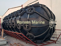
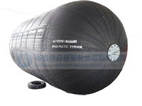
Pneumatic rubber fenders manufactured based floating pneumatic rubber fender standard ISO 17357-high pressure. Yokohama floating pneumatic rubber fenders are filled with air in cylindrical body used for a inflatable bumper for boats, navy ships vessels and marine barges STS ship to ship transfers, STB ship to dock berthing. Since floating yokohama pneumatic rubber fenders are made of rubber, oil & water resistance, are widely applied to gas energy, marine field. Pneumatic rubber fenders can be deflected to 60%, showing a stable performance among the marine fenders systems.
Why Choose Pneumatic Rubber Fenders?
- Standard Compliance: Fully complies with ISO 17357 and PIANC GUIDELINES.
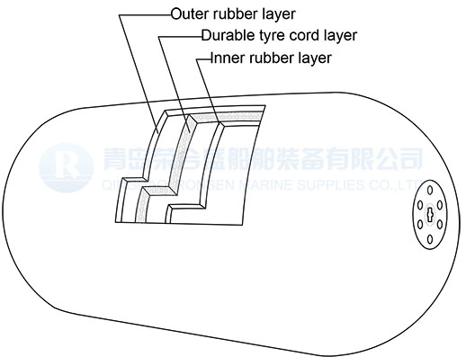
- Structure: Cylindrical body with multi-layer rubber and cord reinforcement.
- Performance: High energy absorption, low reaction force, minimal hull pressure.
- Durability: Resistant to abrasion, UV radiation, saltwater, and oil.
How to Choose the Right Pneumatic Fender
1. Determine Energy Requirement – P50 or P80?
| Application | Recommended Class | Why |
| Barges, pontoons, small workboats | P50 | Lower berthing energy; cost-effective |
| Tankers, bulk carriers, container ships (>10,000 DWT) | P80 | Higher energy absorption per ISO 17357 table |
| Ship-to-ship (STS) transfers | P80 | Dual-vessel movement doubles impact energy |
| Submarine tender operations | P80 + ribbed cover | Controlled deflection + abrasion resistance |
2. Match Size to Vessel Tonnage
| Vessel Size | Recommended Fender Size (Dia. x Length) | Typical GEA |
| <500 GT | 500 x 1000 mm | 6.4 KJ |
| 500-2,00 GT | 700 x 1500 mm | 24.5 KJ |
| 2,000-10,000 GT | 1000 x 2000 mm | 49 KJ |
| 10,000-50,000 GT | 1700 x 3000 mm | 191 KJ |
| 50,000-100,000 GT | 2500 x 4000mm | 663 KJ |
| 100,000-300,000 GT | 3300 x 6500mm | 1817 KJ |
| 300,000+GT (VLCC) | 4500 x 9000mm | 2746 K J |
Vessel above follow ISO 17357-1:2014 GEA tables at 60% deflection, initial internal pressure 50 kPa (P50) or 80 kPa (P80).
3. Don’t Forget the Angle
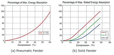
Pneumatic fenders maintain >70% energy absorption at 15 approach angle (per ISO 17357 oblique compression test). For berths with frequent angled approaches, size up one class or add a second fender in tandem.
Pneumatic Fenders Classification
According to pneumatic rubber fenders international standard, floating pneumatic rubber fenders system are grouped into two. And from appearance, fenders for ships and marine are classified another two:
- Initial Pressure 50 Kpa, P50 pneumatic fender
- Initial Pressure 80 Kpa, P80 pneumatic fender
- Type I, CHN Type, with chains and tire nets pneumatic marine rubber fender
Type II, Sling Type, without chains and tire nets pneumatic rubber fender
Pneumatic Rubber Fenders Construction
– High tear strength inner rubber layers
– rubber dipped synthetic tire cord reinforced layers
– Durable outer rubber layers, end accessories and fittings
Types of Floating Pneumatic Rubber Fenders: Sling, Ribbed & Yokohama
To meet diverse maritime needs, we manufacture and supply three main types of floating pneumatic rubber fenders for vessels and barges:
- Navy grey sling type
Navy pneumatic rubber fenders are colored in navy grey, normally for navy ships, warships in sling type, without chains and tire nets with inflated initial pressure at either 50 Kpa or 80 Kpa.
“leader” in China. Ribbed rubber pneumatic fenders have a lighter weight, with chains and tire nets of traditional pneumatic rubber fenders replaced by prominent ribbed stripes.
- Yokohama type
Yokohama type marine pneumatic rubber fenders or yokohama pneumatic fenders are sometimes meant pneumatic rubber fenders directly referring to international i 17357. Pneumatic fenders are produced adopting Japan Yokohama technology, with distinctive and efficient assembling line equipped with xupscale testing machinery.
Semi-submerged vertical submarine pneumatic rubber fenders are filled with water installed between berths and submarines for docking purpose.
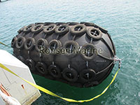
Floating Pneumatic Marine Rubber Fender: Key Advantages Over Solid Rubber Fenders
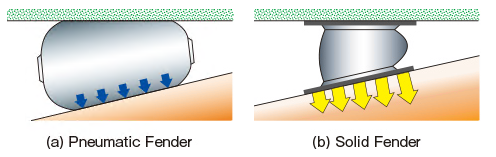
When ships berth at docks or during Ship-to-Ship (STS) transfers, the initial contact is rarely head-on—it’s often at an oblique angle. This is where pneumatic fenders outperform traditional solid rubber fenders. Here’s why:
✅
1. Superior Performance at Oblique Angles
Unlike solid rubber fenders, which lose up to 50% of their energy absorption capacity under angled compression, pneumatic fenders maintain consistent performance. Their cylindrical air-filled body and flexible rubber layers allow them to distribute impact loads evenly along the vessel’s hull, even at angles up to 15 degrees.
✅ 2. Self-Floating & Zero Maintenance
Buoyancy: The internal air chamber provides permanent buoyancy—no inflation required.
Durability: Constructed with high-tensile synthetic tire cords and abrasion-resistant rubber skins, they resist UV, seawater, and physical damage.
Maintenance: Unlike inflatable fenders, they won’t leak or deflate, ensuring reliable protection year after year.
✅ 3. Cost-Effective & Space-Saving
Smaller Footprint: Due to high energy absorption efficiency, you often need a smaller size compared to solid fenders for the same job.
Lightweight Installation: Easier to handle and install using standard chains and accessories, reducing labor costs.
Ready to upgrade your marine protection system? [Contact Ronsen Marine Experts] for a free consultation or product specification sheet.
Floating Yokohama Pneumatic Rubber Fenders Performance Table
In accordance with requirements of ISO 17357-1 high pressure yokohama type floating pneumatic rubber fenders, marine pneumatic rubber fenders performed at pressure of 50 Kpa and 80 Kpa only, which are listed in below sheet demonstrates sizes of pneumatic rubber fenders from diameter 0.5 m ~4.5 m , 1.0 m ~12.0 m in length, we are now available to supply below sizes of pneumatic rubber fenders.
| Initial Pressure | P50 | P80 | ||||
| Nominal size diameter x length mm | Guaranteed energy absorption(GEA) | Reaction force at GEA deflection(R) | Hull pressure(Internal pressure) at GEA deflection(P) | Guaranteed energy absorption(GEA) | Reaction force at GEA deflection(R) | Hull pressure(Internal pressure) at GEA deflection(P) |
| Minimum value at deflection 60±5% | Tolerance±10% kN | Reference value kPa | Minimum value at deflection 60±5% | Tolerance±10% kN | Reference value kPa | |
| 500 x 1000 | 8 | 64 | 132 | 8 | 85 | 174 |
| 600 x 1000 | 8 | 74 | 126 | 11 | 98 | 166 |
| 700 x 1500 | 17 | 137 | 135 | 24 | 180 | 171 |
| 1000 x 1500 | 32 | 182 | 122 | 45 | 239 | 160 |
| 1000 x 2000 | 45 | 257 | 132 | 63 | 338 | 174 |
| 1200 x 2000 | 63 | 297 | 126 | 88 | 390 | 165 |
| 1350 x 2500 | 102 | 427 | 130 | 142 | 561 | 170 |
| 1500 x 3000 | 153 | 579 | 132 | 214 | 761 | 174 |
| 1700 x 3000 | 191 | 639 | 128 | 267 | 840 | 168 |
| 2000 x 3500 | 308 | 875 | 128 | 430 | 1150 | 168 |
| 2500 x 4000 | 663 | 1381 | 137 | 925 | 1815 | 180 |
| 2500 x 5500 | 943 | 2019 | 148 | 1317 | 2653 | 195 |
| 3300 x 4500 | 1175 | 1884 | 130 | 1640 | 2476 | 171 |
| 3300 x 6500 | 1814 | 3015 | 146 | 2532 | 3961 | 191 |
| 3300 x 10600 | 3067 | 5257 | 158 | 4281 | 6907 | 208 |
| 4500 x 9000 | 4752 | 5747 | 146 | 6633 | 7551 | 192 |
| 4500 x 12000 | 6473 | 7984 | 154 | 9037 | 10490 | 202 |
Floating Yokohama Fenders Pressure Requirements
Referred to pressure of one pneumatic rubber fender for marine, there are initial pressure without deflection of one pneumatic rubber fender and pneumatic fenders at 60% deflection, hull pressure at related deflection, and safety valve pressurings as well as tested pressure of a pneumatic rubber fenders to be discussed below.
Pressure of P50 Performance
| Nominal size diameter x length mm | International pressure | Minimum endurable pressure | Safety-value Pressure setting kPa | Testing pressure at 0% deflection kPa | ||
| at 0% deflection kPa | at 60% deflection kPa | at 0% deflection kPa | at 60% deflection kPa | |||
| 500 x 1000 | 50 | 132 | 300 | 462 | - | 200 |
| 600 x 1000 | 50 | 126 | 300 | 441 | - | 200 |
| 700 x 1500 | 50 | 135 | 300 | 473 | - | 200 |
| 1000 x 1500 | 50 | 122 | 300 | 427 | - | 200 |
| 1000 x 2000 | 50 | 132 | 300 | 462 | - | 200 |
| 1200 x 2000 | 50 | 126 | 300 | 441 | - | 200 |
| 1350 x 2500 | 50 | 130 | 300 | 455 | - | 200 |
| 1500 x 3000 | 50 | 132 | 300 | 462 | - | 200 |
| 1700 x 3000 | 50 | 128 | 300 | 448 | - | 200 |
| 2000 x 3500 | 50 | 128 | 300 | 448 | - | 200 |
| 2500 x 4000 | 50 | 137 | 350 | 480 | 175 | 250 |
| 2500 x 5500 | 50 | 148 | 350 | 518 | 175 | 250 |
| 3300 x 4500 | 50 | 130 | 350 | 455 | 175 | 250 |
| 3300 x 6500 | 50 | 146 | 350 | 511 | 175 | 250 |
| 3300 x 10600 | 50 | 158 | 350 | 553 | 175 | 250 |
| 4500 x 9000 | 50 | 146 | 350 | 511 | 175 | 250 |
| 4500 x 12000 | 50 | 154 | 350 | 539 | 175 | 250 |
Pressure of P80 Performance
| Nominal size diameter x length mm | International pressure | Minimum endurable pressure | Safety-value Pressure setting kPa | Testing pressure at 0% deflection kPa | ||
| at 0% deflection kPa | at 60% deflection kPa | at 0% deflection kPa | at 60% deflection kPa | |||
| 500 x 1000 | 80 | 174 | 132 | 480 | 609 | - |
| 600 x 1000 | 80 | 166 | 126 | 480 | 581 | - |
| 700 x 1500 | 80 | 177 | 135 | 480 | 620 | - |
| 1000 x 1500 | 80 | 160 | 122 | 480 | 560 | - |
| 1000 x 2000 | 80 | 174 | 132 | 480 | 609 | - |
| 1200 x 2000 | 80 | 166 | 126 | 480 | 581 | - |
| 1350 x 2500 | 80 | 170 | 130 | 480 | 595 | - |
| 1500 x 3000 | 80 | 174 | 132 | 480 | 609 | - |
| 1700 x 3000 | 80 | 168 | 128 | 480 | 588 | - |
| 2000 x 3500 | 80 | 168 | 128 | 480 | 588 | - |
| 2500 x 4000 | 80 | 180 | 137 | 560 | 630 | 230 |
| 2500 x 5500 | 80 | 195 | 148 | 560 | 683 | 230 |
| 3300 x 4500 | 80 | 171 | 130 | 560 | 599 | 230 |
| 3300 x 6500 | 80 | 191 | 146 | 560 | 669 | 230 |
| 3300 x 10600 | 80 | 208 | 158 | 560 | 728 | 230 |
| 4500 x 9000 | 80 | 192 | 146 | 560 | 672 | 230 |
| 4500 x 12000 | 80 | 202 | 154 | 560 | 707 | 230 |
Quality Inspection & Certifications
Our pneumatic rubber fenders are manufactured and tested upon ISO 17357:2002 strictly, can accept inspections from BV, CCS, ABS, LR, DNV-GL etc.

BV Certificate

BV Certificates
Floating Pneumatic Fenders Application & Installation
Pneumatic rubber fenders generally have two main applications for ships: ship to ship transfer and ship to quay operation.
Ship to ship: normally, for lighter weight ships transferring work, smaller pneumatic rubber fenders are enough. But for heavy duty barges or vessels, bigger-sized marine pneumatic rubber fenders with more quantity are necessary. The pneumatic rubber fenders are hung alongside of ships hull with mooring chains or fibre ropes.
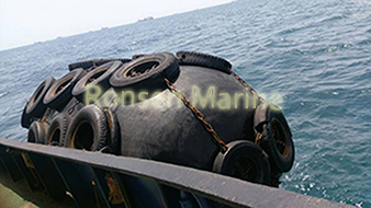
Ship to Ship Installation
Ship to quay: pneumatic rubber fenders are installed side of ports to absorb berthing energy when ships docks. Fenders are hung also by guy chains or ropes, same as ship to ship operation.

Ship Quay Installation
Quick Selection Table:
- Example:” For Vessels under 1,000 DWT: Recommended Size 1.0m x 1.5m (P50);
For Vessels 5,000-10,000 DWT: Recommended Size 2.5m x 4.0m (P80);
FAQ
What’s the floating pneumatic rubber fenders international standard?
Floating pneumatic rubber fenders was basically manufactured and tested upon international standard “ISO 17357 Ships and marine technology-High-pressure floating pneumatic rubber fenders”. This international standard specifies the material, performance and dimensions of pneumatic rubber fenders, which are intended to be used for the berthing and mooring of a ship to another ship or berthing structure. It also specifies the test and inspection procedures for high-pressure floating pneumatic rubber fenders.

ISO 17357
What are pneumatic rubber fenders testing and inspections?
The general inspection tests for a floating yokohama pneumatic rubber fender include material test of rubber, both outer rubber and inner rubber. It should be conducted in accordance with the specifications given in below table and the results shall satisfy the requirements in the table.

And the dimensional inspection. The dimension of all the fenders shall be inspected at the initial internal pressure and the results shall be within the following tolerances:
____ length: +10%, -5%
____ diameter: +10%, -5%
The air-leakage test shall be conducted on all fenders at initial pressure for more than 30 min, and the test results shall confirm that there is no air leakage.
How to proceed floating pneumatic fenders hydrostatic-pressure test?
The hydrostatic-pressure test shall be performed for 10 min at the hydrostatic pressure shown as ”Test pressure at 0% deflection in below tables and there shall be no leakage of water and no defects during the test. The frequency of the test shall be one per 20 fenders of each size and pressure. Circumferential and longitudinal lengths shall be measured at 10 kPa pressure and at the test pressure shown in below table. The temporary elongation shall be as follows.
____ Maximum circumferential temporary elongation: 10%
____ Maximum longitudinal temporary elongation: 10%
Why select pneumatic rubber fenders comparing with marine rubber fenders?
Floating fenders provide nice buffer force comparing with solid marine rubber fenders which can effectively absorb the impact force of ships berthing. Because its interior is air, the compressibility of air allows the fender to disperse energy through deformation when subjected to compression. Its superior energy absorption and reaction force performance to decrease the outer force amid the two ships or ship to quay, softer to prevent the appearance and structure of marines, ships, which is much suitable for sts transfers. Floating Pneumatic Rubber Fenders has high elasticity, can adapt to ships of different shapes and sizes, has a large contact area with ships, can reduce pressure on the surface of ships, and lower the risk of ship damage.The marine rubber fenders are normally applied to ship to quay operations to distribute the collision force and prevent the port structure, it is economical but the reaction force will decrease after sometime.
What are the advantages of pneumatic rubber fenders vs foam filled fenders?
High energy absorption and low reaction force: Pneumatic Rubber fenders absorb more impact energy and have less reaction force at the same size, making them particularly suitable for large/sensitive ships (such as LNG ships) to ship or high dry side berthing; Foam filled fenders also have high energy absorption, but the reaction gradient is more gentle, and the compression of 60% is still stable, which is suitable for frequent berthing and large tidal range environment.
Maintenance and reliability: Floating pneumatic rubber fenders require regular checks of air pressure, and there is a risk of air leakage/explosion, resulting in high maintenance costs; The foam fender is a solid closed hole structure, with no sinking, maintenance free and explosion risk, and its service life is usually 10 – 15 years (about 1 – 5 years for inflatable fenders).
Installation and adaptability: Pneumatic fenders float well with waves, self centering and fitting the hull, suitable for dynamic STS (ship to ship) operations; The foam fenders have buoyancy and are not affected by the tide level. They are suitable for fixed wharves, floating wharves or wind power platforms and other scenes that need stable contact.
Durability and safety: foam filled fenders are puncture resistant, UV resistant, seawater resistant, and still effective when damaged; The outer rubber of the inflatable fender is prone to scratches and loss of cushioning due to internal pressure failure, but some models can be repaired on site.
Cost: Pneumatic fenders are initially expensive to purchase (about 1.5-2 times) and easy to install; The initial cost of foam filled fender is medium, and the long-term TCO is lower (maintenance free+long life).
How to Design and the Selection of Pneumatic Fenders?
The design and selection of floating fenders can be confirmed as per the maximum energy absorption of specific conditions. We should calculate and compare the requirements for the energy of the following condition. The kinetic energy when the ship berthing or after berthing, the energy of relative motion of ship to ship and ship to wharf.
Ship to ship operation of floating pneumatic fenders
Following the follow chart which simply demonstrate the procedure of floating fenders selection.

There is a quick reference to do the floating pneumatic rubber fender selection tentatively as per the listed OCIMF table. If the energy absorption of the tentative selected yokohama fender(Ef) is larger than the calculatedd berthing energy (E). It means that a suitable floating fender selection has been made. If the Yokohama fenders energy absorption capacity is less than the calculated berthing energy. The selected yokohama fenders should be upgrated and selected again.

OCIMF Table Selection of Floating Pneumatic Rubber Fenders
It is a quick reference selection based on 50 kPa (Pneumatic 50) and calm condition, Equivalent Displacement coefficient (C) should be calculated firstly, then make the tentatively selection as per OCIMF ship to ship transfer guide.
C= 2 x Displacement ShipA x Displacement ShipB/( Displacement ShipA + Displacement ShipB)
Berthing Energy Calculation of Yokohama Fenders
The berthing energy can be calculated by the following formula:
![]()
Where:
E =Berthing Energy (in KNm or ton/m)
= Equivalent Displacement Coefficient
= Relative Approaching Velocity
= Eccentricty Factor
SF = Safety Factor
![]()

![]()
![]()
Where:
= Water displacement of the berthing Ship A ( tons )
= Water displacement of the berthing Ship B ( tons )
= Added mass coefficient of Ship A
= Added mass coefficient of Ship B
Added Mass Coefficient
or

Where:
d = Full load draft (m, ft)
B = Molded Breadth (m, ft)
= Block coefficient
Safety Factor
A safety factor (SF) value from 1.0 to 2.0 for the berthing energy shall be considered for abnormal berthing conditions.
Eccentricity Factor


Where:
I = Radius of rotation of the vessel (usually 1/4 of the vessel’s length )
r = Distance of the line paralleled to wharf measured from the vessel’s center of gravity to the point of contact
a = the angle degree
= Block coefficient
L = Length of ship
Relative Approaching
The berthing energy needs to be calculated considering weather conditions, categorized by the three conditions calm, moderate and rough, and the approaching velocity to calculate the berthing energy are assumed to be as the follow table. These information are obtained from various industry references and standards.

Ship to Quay Operation of Pneumatic Rubber Fenders
The selection and installation of floating pneumatic rubber fenders (marine fendering) system for a quay is determined based on several design parameters for each ship berthing and mooring condition
The energy can be calculated by the following formula:
![]()
Where:
E = Berthing Energy ( in KNm or ton/m)
M = Displacement (ton)
V = Berthing Velocity (m/s)
= Eccentricity Factor
= Vitural mas factor

d = Full load draft (m, ft)
B = Molded Breadth (m. ft)
SF = Safety Factor
= Berthing configuration factor
This is the portion of berthing energy which is absorbed by the cushion effect of water between the approaching vessel and the quay wall. The smaller the draft of the vessel is, or the larger the under keel clearance, the mor trapped water can escape under the vessel, and would give a higher
value. Also, if the berthing angle of the vessel is greater than 5 degree, we can consider
= 1
= Softness coefficient
This is the portion of berthing energy which is absorbed by the demonstration of the vessel’s hull and fender. When a soft fender is issued
= 0.9
Written/verified by Ronsen Marine engineering team, Qingdao, 15 yrs fender mfg