

What Is a Pneumatic Rubber Fender?
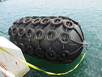
Pneumatic Rubber Fenders
A pneumatic rubber fender is a hollow, cylindrical marine buffer with hemispherical ends, built from multiple layers of synthetic-tyre-cord-reinforced rubber and filled with compressed air. It floats at the waterline, tethered to a vessel or a berth by slings, chains, or a chain-tire net (CTN), and rises and falls with the tide without any fixed mounting.
Its job is to absorb the kinetic energy of a vessel as it comes alongside another ship or a quay, then return most of that energy as it re-expands—so the hull and the berthing structure see a soft, progressive load instead of a hard impact.
The key word is pneumatic. Unlike solid rubber fenders, which rely on the stiffness of the rubber itself, a pneumatic fender relies on the compressibility of the air inside. That is what gives it a high energy absorption and a low reaction force for the same physical size, and it is why the device is described by its international standard as a high-pressure floating pneumatic rubber fender.
Why “Yokohama Fender” and “Yokohama Type” Mean Different Things
The term Yokohama fender is widely used in the industry as a generic name for this product. It originates from The Yokohama Rubber Co., which developed the pneumatic fender in the 1950s.
Two distinctions matter for buyers and for search:
| Term | What it means | How to use it |
| YOKOHAMA® fender | A fender made by The Yokohama Rubber Co., a registered trademark | Only when referring to that manufacturer’s product |
| Yokohama type fender / Yokohama pneumatic fender | A generic description of the pneumatic, air-filled design | Acceptable as a descriptive phrase, but keep it out of the page title and meta description |
| Pneumatic rubber fender | The neutral, standard-compliant product name | Use this as the primary name on product and article pages |

Pneumatic Rubber Fenders Construction
Using a third party’s trademark as a generic product name in a title can create both legal and indexing problems. This article uses pneumatic rubber fender as the primary term and mentions Yokohama type only in passing.
How a Pneumatic Rubber Fender Works
The whole device is a closed air spring. When a hull presses against it, the air column shortens, internal pressure rises uniformly, and the energy of the impact is converted into air pressure and elastic strain in the rubber and cord layers. When the vessel retreats, the air re-expands and the fender recovers its shape, ready for the next contact.
The Energy Absorption Cycle, Step by Step
Step 1 — Vessel approaches: The fender floats at the point of hull contact, self-centring with the waterline.
Step 2 — Hull makes contact: Compression begins. The initial pressure is 50 kPa (P50) or 80 kPa (P80).
Step 3 — Air column shortens: Internal pressure rises progressively as the fender is compressed, typically to a rated deflection of 60% of the original diameter.
Step 4 — Kinetic energy is absorbed: Energy absorption is the integral of reaction force over deflection, measured under a parallel compression test at a compression rate not exceeding 80 mm/min.
Step 5 — Reaction force returns to the hull: Because the force-deflection curve rises gently at first and then more steeply near 60%, the hull is cushioned rather than struck.
Step 6 — Vessel retreats: The air re-expands and the fender rebounds elastically, requiring no break-in cycle.
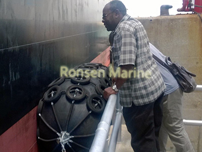
Pneumaitc Rubber Fenders for STQ
Why the Reaction Force Stays Low
A solid rubber fender resists the hull with material stiffness. A pneumatic fender resists it with gas compressibility. Air has no fixed shape and no high initial modulus, so the force-deflection curve starts soft and only steepens near the rated deflection. That “soft entry” is the core advantage, and it is what makes pneumatic fenders suitable for large, thin-shell or sensitive hulls where structural stress must be kept low.
The trade-off is that the pressure must be monitored. A fender under-inflated by a small amount can deliver materially less energy absorption at rated deflection, which is why ISO 17357-1:2014 specifies both the initial pressure and the test procedure.
Performance at an Angle
Ships rarely berth perfectly head-on. The cylindrical, flexible body of a pneumatic fender continues to distribute load evenly along the hull at approach angles up to 15°, per the angular compression test defined in ISO 17357-1:2014. This is one of the principal differences between pneumatic fenders and many solid fender profiles, which lose performance rapidly under angled compression.
Construction: The Three Layers
A pneumatic rubber fender is built from the outside in as a multilayer cylinder, with all layers vulcanized together under high pressure and hardened at high temperature. The three structural layers are specified by ISO 17357-1:2014.
Outer Rubber Layer
The outer rubber is the abrasion-resistant skin. Its function is to protect the cord layers and the inner rubber from seawater, UV, ozone, and the mechanical wear of repeated contact with hulls and quay faces. Standard colour is black; grey and other colours are available on request, for example for naval use, though the material property requirements differ for non-black outer rubber.
The minimum physical property requirements for the outer rubber layer, taken from ISO 17357-1:2014, are summarised below.
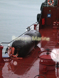
Pneumatic Rubber Fenders for STS
Synthetic-Tyre-Cord Reinforcement Layers
The reinforcement layers carry the structural load. Synthetic tyre cord is arranged at an optimum angle so that internal pressure is held and stress is distributed evenly; this is also what allows the fender to remain shape-conformant under compression. Each layer is rubber-coated on both sides, which isolates the individual cords and reduces friction and wear as the body bends, compresses and stretches. The cord density and tensile strength are confirmed as part of the prototype test programme.
Inner Rubber Layer (Air-Tight Liner)
The inner rubber is the air seal. Its primary function is to retain the pressurised air inside the body at the rated working pressure, which is what allows the fender to deliver a consistent guaranteed energy absorption and reaction force. Any loss of integrity in this layer reduces performance and makes pressure monitoring a safety requirement rather than a maintenance option.
End Fittings, Valves and Netting
At one or both ends, a steel bead ring secures the cord layers and a steel flange carries the valves and lifting points. Fenders of 2500 mm diameter and above are fitted with a safety valve that releases air if the pressure rises above the design limit. Metal accessories—shackles, towing rings, swivels and chain nets—are typically hot-dip galvanised or stainless steel for seawater corrosion resistance.
| Test item | Outer rubber | Inner rubber |
| Tensile strength (ISO 37), before aging | 18 MPa or more | 10 MPa or more |
| Elongation (ISO 37), before aging | 400% or more | 400% or more |
| Hardness (ISO 7619-1) | 60 ±10 (Type A) | 50 ±10 (Type A) |
| Tensile strength after aging | Not less than 80% of original | Not less than 80% of original |
| Elongation after aging | Not less than 80% of original | Not less than 80% of original |
| Tear resistance (ISO 34-1) | 400 N/cm or more | No requirement |
| Compression set (ISO 815-1) | 30% or less | No requirement |
| Static ozone aging (ISO 1431-1) | No cracks | No requirement |
Note: the aging condition is air-oven aging at 70°C ±1°C for 96 h. These are minimum requirements of the standard; actual production values vary by manufacturer.
Fender Types: Net Type vs Sling Type
ISO 17357-1:2014 classifies pneumatic fenders by construction. The two production types are Type I and Type II.
| Type | Construction | Best suited to | Advantages | Limitations |
| Type I — Chain-Tire-Net (CTN) | Chains with tyres or rubber sleeves around the body | Permanent berths, high-frequency ports, STS transfer of oil and LNG, rough weather and abrasive quay faces | Excellent abrasion resistance; long service life; distributes load over the body | Heavy; can mark sensitive hulls; slower to deploy |
| Type II — Sling type | No chain-tire net; lifting eyes and slings instead | Yachts, naval vessels, cruise ships, temporary berthing, quick deployment | Lightweight; non-marking options; easy to handle and install | Less abrasion protection; requires careful operation near sharp edges |
Derived Types
Manufacturers offer variations built on the same pneumatic principle. Common examples are ribbed fenders, which replace chains and tyres with prominent ribbed stripes to reduce weight; naval grey fenders, finished in non-marking grey for warships; and hydro-pneumatic fenders, which are partly filled with water for submarine berthing. These are trade descriptions, not separate classifications under ISO 17357-1:2014.
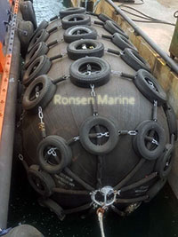
Floating Pneumatic Rubber Fenders
ISO 17357-1:2014: What the Standard Actually Requires
ISO 17357-1:2014, Ships and marine technology — Floating pneumatic rubber fenders — Part 1: High pressure, is the current international specification for high-pressure floating pneumatic rubber fenders. It specifies the material, performance and dimensions of fenders intended for the berthing and mooring of a ship to another ship or to a berthing structure, and it specifies the test and inspection procedures.
The standard was published on 15 January 2014 and revised ISO 17357:2002, which has since been withdrawn. References to the 2002 edition should not appear on a current datasheet, purchase order or certificate of conformity.
What the Standard Defines
| Item | Requirement in the standard |
| Fender types | Type I (net type) and Type II (sling type) |
| Initial internal pressure | 50 kPa (P50) and 80 kPa (P80) for high-pressure fenders |
| Performance | Guaranteed Energy Absorption (GEA), reaction force at GEA deflection, hull surface pressure |
| Construction | Outer rubber, synthetic-tyre-cord reinforcement, inner rubber liner; vulcanized |
| Tolerances | Length +10% / −5%; diameter +10% / −5% |
| Air-leakage test | All fenders, at initial pressure, for at least 30 min, no leakage |
| Hydrostatic-pressure test | 10 min at test pressure; temporary elongation ≤10% |
| Durability | 3000 compression cycles with no cracks and no reduction in GEA |
| Marking | Nominal size, initial pressure, type, standard and manufacturer identification |
| Independent inspection | Optional inspection or evaluation by a classification society |
The Five Tests That Matter at Delivery
Material test: Tensile strength, elongation, hardness, tear resistance, compression set and ozone resistance of both outer and inner rubber, to the values in Section 3.
Dimensional inspection: Length and diameter measured at initial internal pressure, checked against the +10% / −5% tolerance.
Air-leakage test: All fenders at initial pressure for at least 30 min; the result must confirm no air leakage.
Hydrostatic-pressure test: 10 min at the test pressure shown for 0% deflection; circumferential and longitudinal temporary elongation must not exceed 10% each.
Prototype tests (Clause 8): Parallel compression, angular compression, durability (3000 cycles), compression-recovery, and puncture resistance per the static puncture test of ISO 12236.
The frequency of the hydrostatic-pressure test is one fender per 20 fenders of each size and pressure. The energy absorption and reaction force values are taken as the mean of two test records, with a 5-minute interval between them.
P50 vs P80: Choosing Initial Pressure
For the same diameter and length, the only variable that changes the performance class is the initial internal pressure. P50 is 50 kPa; P80 is 80 kPa. You do not change the size to change the performance class—you change the initial pressure.
| Parameter | P50 — 50 kPa | P80 — 80 kPa |
| Initial pressure | 50 kPa | 80 kPa |
| Energy absorption | Baseline GEA | Approximately 35–40% higher than P50 |
| Reaction force | Lower | Higher |
| Hull surface pressure | Lower | Higher |
| Typical use | LNG carriers, aluminium hulls, yachts, naval vessels, sensitive coatings | VLCCs, large tankers, high approach velocity, limited fender count |
| Selection constraint | Where hull or structure is sensitive | Must be matched to the hull allowable pressure and wharf capacity |
A P50 body must never be inflated to 80 kPa. The cord-layer angle, end-ring design and safety factors differ between the two ratings, so the classification is not interchangeable.
A Worked Comparison
Using the performance figures published by Henger for ISO 17357 pneumatic fenders, the difference between P50 and P80 is visible at the same nominal size:
| Nominal size (mm) | Initial pressure | GEA at 60% deflection (kJ) | Reaction force (kN) | Hull pressure (kPa) |
| 2000 × 3500 | P50 — 50 kPa | 308 | 875 | 128 |
| 2000 × 3500 | P80 — 80 kPa | 430 | 1150 | 168 |
| 2500 × 4000 | P50 — 50 kPa | 663 | 1381 | 137 |
| 2500 × 4000 | P80 — 80 kPa | 925 | 1815 | 180 |
| 3300 × 6500 | P50 — 50 kPa | 1814 | 3015 | 146 |
| 3300 × 6500 | P80 — 80 kPa | 2532 | 3961 | 191 |
These figures are one manufacturer’s published values for a nominal size. They illustrate the sizing method; they are not a substitute for a calculation against the design berthing energy of a specific berth.
How to Size a Pneumatic Rubber Fender
The most common mistake in fender selection is to choose a size from DWT or vessel length alone. Fender capacity is determined by the design berthing energy of the operation, so the calculation must come first.
The Berthing Energy Formula
The PIANC method gives the design berthing energy as:
E = ½ × Me × V² × Ce × Cm × Cs × Cc
Where:
E = Berthing energy, in kJ
Me = Effective vessel mass
V = Approach velocity
Ce = Eccentricity coefficient
Cm = Added mass coefficient
Cs = Softness coefficient
Cc = Configuration or berth coefficient
The Four-Step Selection Method
Step 1 — Calculate the design berthing energy: Use the formula above with the actual displacement, approach velocity and site coefficients for the berth. Approach velocity must reflect the weather condition: calm, moderate or rough.
Step 2 — Select for GEA: Choose a fender whose GEA at 60% deflection is greater than the design berthing energy multiplied by the applicable safety factor, typically 1.1 to 1.25 for abnormal berthing conditions.
Step 3 — Check reaction force and hull pressure: Confirm that the reaction force at GEA does not exceed the allowance of the hull plating or the wharf structure, and that the hull pressure reference value is within the vessel’s shell limit.
Step 4 — Choose P50 or P80 and type: Select P50 where the hull or structure is sensitive; P80 where the berthing energy is high. Choose Type I for abrasion resistance or Type II where marking must be avoided.
Sizing by Vessel Category
The following are commonly used starting points, not specifications. Every application should be verified against the calculated berthing energy.
| Vessel category | Typical starting size |
| Tug / pilot | 500 × 1000 to 1000 × 2000 mm |
| Feeder / ro-ro | 1500 × 3000 to 2000 × 3500 mm |
| Panamax / Aframax | 2500 × 4000 to 2500 × 5500 mm |
| VLCC / LNG / heavy STS | 3300 × 6500, 3300 × 10600, 4500 × 9000 mm |
For an equivalent displacement coefficient C in ship-to-ship transfer, the OCIMF relationship is C = 2 × Displacement A × Displacement B / (Displacement A + Displacement B), where the added mass coefficients of the two vessels are taken into account.
Where Pneumatic Rubber Fenders Are Used
The floating, self-centring behaviour of pneumatic fenders makes them suitable wherever the waterline moves or where no fixed fender can be installed.
Ship-to-ship transfer: Crude, product and LNG tankers during lightering and transfer operations; small vessels can use smaller fenders, while heavy barges and large vessels require larger sizes and greater numbers.
Ship-to-quay berthing: Fenders hung from the berth face by guy chains or ropes to absorb berthing energy as ships dock.
Offshore platforms and FPSOs: Boat landings where the fender must follow the waterline and accommodate relative motion.
Tidal jetties and ferry terminals: Sites with a large tidal range, where a fixed fender would be submerged at high water and high above the hull at low water.
Naval alongside replenishment: Non-marking grey sling-type fenders for warships and auxiliary vessels.
Submarine berthing: Hydro-pneumatic variants installed between the berth and the submarine.
Pneumatic vs Foam-Filled Fenders
The two products are often compared because they both float, but they work on different principles and are selected for different reasons. The following comparison is a working-principle summary and should be used as a starting point for a specification, not as a statement of performance.
| Aspect | Pneumatic rubber fender | Foam-filled fender |
| Energy medium | Compressed air | Closed-cell foam compression |
| Deflation risk | Present if the skin or valve is breached | None |
| Reaction force | Very low | Moderate to higher |
| Performance at an angle | Uniform pressure distribution to 15° (ISO angular compression test) | Slightly less uniform |
| Maintenance | Periodic pressure checks and valve inspection | None required for the core |
| Failure mode | Loss of pressure on puncture; repairable | Remains buoyant when damaged |
| Transport and storage | Deflatable, compact | Bulky, solid |
| Best fit | STS, offshore, tidal ranges, dynamic operations | Fixed berths, unmanned sites, debris-risk environments |
The choice is therefore not about which is “better” in the abstract. It is about whether the application values the low reaction force and compact transport of a pneumatic fender, or the maintenance-free reliability of a foam-filled unit.
Installation, Pressure Checks and Service Life
Installation and Commissioning
Inspection before installation: Check the initial air pressure, valve condition and the outer surface for cuts, cracks or signs of pressure loss.
Fixing and hanging: Use chains, synthetic ropes or brackets as required by the design. Ensure the load is distributed evenly across the slings or net.
Inflation and adjustment: Inflate to the manufacturer’s specified pressure for the rated initial pressure, then check for leakage.
Safety check: Verify end fittings, shackles and hanging points are secure before the vessel berths.
A Practical Maintenance Schedule
| Frequency | Check |
| Before each operation | Visual inspection for cuts, cracks or pressure loss |
| Monthly | Check and record air pressure against the value stated on the product label |
| Quarterly | Inspect chains, slings, shackles and end fittings for wear and corrosion |
| Annually | Review records against the initial pressure tolerance and the results of the air-leakage test |
The initial pressure tolerance generally accepted in the industry is ±5%, with tighter tolerances preferable. A fender under-inflated by a small amount can deliver materially less energy absorption at rated deflection, so the recorded pressure should be treated as part of the safety documentation.
What “Service Life” Means
Service life depends on the operating conditions: the number of fenders in use, the frequency of compression, the abrasion exposure of the site, and the maintenance discipline. It should not be quoted as a fixed number without those conditions attached. The relevant measure in ISO 17357-1:2014 is the durability test—3000 compression cycles with no cracks and no reduction in GEA—rather than a calendar age.
Frequently Asked Questions
Q: What is the difference between a pneumatic fender and a solid rubber fender?
A: A solid rubber fender resists impact through the stiffness of the rubber itself. A pneumatic fender resists it through the compressibility of the air inside. For the same size, the pneumatic version offers higher energy absorption with lower reaction force, and it maintains performance at approach angles up to 15° per the ISO angular compression test.
Q: Is “Yokohama fender” the same as “pneumatic rubber fender”?
A: No. YOKOHAMA is a registered trademark of The Yokohama Rubber Co. Yokohama type is a generic description of the pneumatic, air-filled design. Pneumatic rubber fender is the neutral, standard-compliant product name and should be used as the primary term on datasheets and web pages.
Q: What does ISO 17357-1:2014 actually specify?
A: It specifies the material, performance and dimensions of high-pressure floating pneumatic rubber fenders intended for ship-to-ship and ship-to-quay berthing, together with the test and inspection procedures. It defines Type I and Type II, the initial pressures of 50 kPa and 80 kPa, the guaranteed energy absorption, reaction force and hull pressure, and the requirements for material, dimensional, air-leakage and hydrostatic-pressure tests.
Q: How is fender size chosen?
A: By calculating the design berthing energy using the PIANC method—displacement, approach velocity and the eccentricity, added mass, softness and configuration coefficients—then selecting a fender whose GEA at 60% deflection exceeds that energy multiplied by the applicable safety factor. DWT and vessel length are not, by themselves, sizing inputs.
Q: What is the difference between P50 and P80?
A: P50 is an initial internal pressure of 50 kPa; P80 is 80 kPa. At the same nominal size, P80 provides approximately 35–40% more energy absorption but returns a higher reaction force and higher hull pressure. A P50 body must not be inflated to 80 kPa because the cord-layer angle and end-ring design differ.
Q: Do all pneumatic fenders need a safety valve?
A: Fenders of 2500 mm diameter and above are equipped with a safety valve to release excess pressure in the event of accidental over-compression. Smaller diameters may be fitted with a valve on request.
Q: What is the largest standard ISO 17357 pneumatic fender size?
A: Ø4500 × L12000 mm is the largest commonly catalogued high-pressure size; Ø4500 × L9000 mm is also standard. Larger bespoke units can be manufactured but require prototype testing and classification approval.
Q: Are ISO 17357 fender sizes quoted in inches or millimetres?
A: Always in millimetres in the standard—for example 3300 × 6500 mm. Suppliers may quote imperial equivalents, but the purchase order should use millimetres to avoid ambiguity.
Q: Does a longer length always mean more energy absorption?
A: For the same diameter, energy absorption rises approximately linearly with length. However, reaction force rises with diameter faster than with length, so the two dimensions cannot be traded off without checking both GEA and reaction force against the berth and hull limits.
Q: Can a pneumatic fender be repaired?
A: Yes. Damage to the outer rubber or cord layers can be repaired on site or at a workshop, depending on the extent. Any repair should be followed by a pressure test. The inner rubber liner must be restored to an air-tight condition before the fender is returned to service.
Summary
A pneumatic rubber fender is an air-filled, pressure-resistant marine buffer whose performance comes from the compressibility of the air inside it, rather than from the stiffness of solid rubber. It is built from three vulcanized layers—outer rubber, synthetic-tyre-cord reinforcement and an air-tight inner rubber liner—and is specified by ISO 17357-1:2014 at two initial pressures, 50 kPa (P50) and 80 kPa (P80).
Its advantages are high energy absorption with low reaction force, performance maintained at approach angles up to 15°, self-centring with the tide, and easy handling. Its requirements are correct sizing against the calculated berthing energy, pressure monitoring, and selection of Type I or Type II to match the hull and site conditions.
For procurement, the purchase order should state the standard (ISO 17357-1:2014), nominal size, initial pressure, fender type and accessories, and should call for the material, dimensional, air-leakage and hydrostatic-pressure test records together with the certificate of conformity.
