

What Is a Support Buoy? The Complete Offshore Guide
What Is a Support Buoy? (Simple Definition)
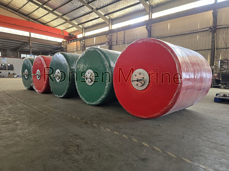
Support Buoys
A support buoy is a foam-filled, steel-reinforced floating device used offshore to suspend hoses, cables, mooring chains and subsea pipelines above the seabed. It reduces mechanical stress on the suspended line and prevents seabed drag, abrasion and fatigue.
Unlike a navigation buoy that guides ships, a support buoy is operational marine infrastructure. Its job is to provide controlled buoyancy and load distribution inside mooring and subsea systems — not to mark a channel.
Also called: surface support buoy, chain support buoy, foam support buoy, chain-through buoy, pick-up buoy.
Support Buoy vs Mooring Buoy vs Navigation Buoy vs Fender
| Type | Primary job | Has navigation lights? | Typical user |
| Navigation buoy | Marks channels and hazards | Yes (IALA colours) | Mariners, port state |
| Mooring buoy | Secures a vessel in place | Sometimes | Harbours, ship crews |
| Support buoy | Lifts and protects hoses, cables, chains | No (unless dual-purpose) | Offshore engineers |
| Foam fender | Absorbs berthing impact energy | No | Terminal operators |
Key distinction: a support buoy’s load path runs through its internal steel member, while a foam fender’s core carries compressive energy absorption. A support buoy is not an energy absorber — though its resilient foam provides useful secondary “self-fendering” when chains or hulls brush against it.
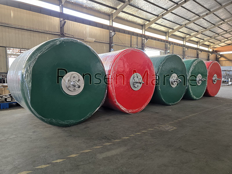
Pick Up Buoys
How a Support Buoy Works (The Load Path)
Understanding the load path is the difference between a buoy that lasts and one that fails:
- Archimedes does the work — the closed-cell foam core displaces a volume of water heavier than the buoy’s own weight plus the load it must lift.
- Net upward force becomes buoyancy reserve, which controls freeboard and ride height.
- The line is partially supported — in an SPM midline, the buoy suspends part of the chain’s submerged weight, reducing ground-chain drag and improving catenary behaviour.
- Steelwork takes the load — safe working load (SWL) is set by the central tube and end flanges, never by the foam. The foam only carries compression and displacement.
- Damage does not sink it — cut the PU skin and seawater meets closed cells. Each cell is sealed, so there is no water ingress and no deflation event.
- Tide and swell tracking — solid displacement means the buoy rises and falls with water level, keeping chain geometry stable without powered adjustment.
Because the steel carries chain tension and the foam only carries compression, the core will not tear under mooring load. This is why foam-filled support buoys are specified for permanent offshore duty.
Construction: Why It Cannot Sink
| Layer | Material | Function |
| Flotation core | Thermo-laminated closed-cell PE or EVA foam | Permanent buoyancy; cells stay dry if skin is breached |
| Internal steelwork | Central tube, gussets, load flanges — hot-dip galvanized or epoxy-coated | Takes tensile and working load |
| Outer skin | Sprayed polyurethane (PU) or polyurea elastomer, often nylon-filament reinforced | Abrasion, UV, seawater and marine-growth resistance |
The foam is cross-linked and thermo-laminated around the steel mandrel so the two act as one monolithic block. Typical PE/EVA core density of 40–70 kg/m³ yields roughly 950–980 N·m³ of net lift in seawater after deducting foam self-weight.
Types of Support Buoys
1. Cylindrical Support Buoy (CB)
High buoyancy, low roll. Central tension member or clevis eyes with the chain attached externally. Used for pipeline floatation and SPM hose support.
2. Chain-Through Support Buoy (CTB)
A steel central tube lets the mooring chain pass through and lock at one or both ends. Excellent load distribution and stability in strong currents. Used as chain-stopper buoys in SPM systems to support chain weight and reduce hawse-pipe tension.
3. Pick-Up Buoy (PU)
Smaller, lightweight unit attached to mooring lines via pick-up ropes or chain plates. Used for retrieving submerged mooring lines, marking subsea assets and providing auxiliary floatation. Easy handling and rapid deployment.
4. Anchor Pendant Buoy
Keeps heavy pendant lines at the surface for diving and ROV access.
5. Surface Foam Support Buoy
PE/EVA closed-cell foam with reinforced PU skin. Puncture-resistant and unsinkable. The general-purpose workhorse across dredging, offshore wind and cable-lay operations.
Key Applications of Offshore Support Buoys
- Oil & gas (SPM systems) — mid-line chain support and tension reduction at tanker loading terminals.
- Subsea cable installation — keeping power and fibre-optic cables afloat during lay operations; wind farm export cables and ROV umbilicals.
- Offshore wind farms — marking turbine locations and guiding SOVs (service operation vessels).
- Dredging operations — supporting discharge pipes and suction hoses.
- Port and harbour installations — temporary hose bridges, salvage support.
- Aquaculture and scientific moorings — instrument pendant flotation.
- Defence and ports — temporary moorings and security barriers.
How to Size a Support Buoy (Buoyancy Calculation)
You do not size a support buoy by berthing energy. You size it by submerged weight. The governing inequality:
B_net = ρ_sw × g × V_displaced − W_buoy ≥ W_submerged_line + F_freeboard
Where ρ_sw ≈ 1025 kg/m³ (seawater); V_displaced is outer volume minus steelwork volume; W_submerged_line is the chain/rope/hose submerged weight (length × unit weight in air − buoyancy); and F_freeboard is the reserved lift to keep the buoy riding at target height.
Practical specification steps:
- Calculate required buoyancy from the submerged weight of chain, rope or hose plus desired freeboard.
- Match chain size — confirm the central tube diameter fits your chain (common sizes: 64 mm, 76 mm, 84 mm).
- Assess environmental conditions — tidal range, current velocity and significant wave height.
- Confirm compliance — PIANC guidelines and OCIMF recommendations for mooring and fender systems.
- Choose materials — hot-dip galvanized or epoxy-coated steelwork for maximum corrosion resistance; UV-stable PU skin to prevent chalking.
- Apply a service factor — most engineers specify 1.5–2× the calculated net buoyancy to retain freeboard through fouling and wear.
Installation: Deployment Sequence
- Confirm water depth, seabed type and swing clearance on site before deployment.
- Drop the anchor or clump weight at the intended location.
- Pay out the ground chain and riser as the deployment vessel moves away, achieving the required scope (mooring manuals commonly recommend 2–3× water depth; high-current sites need more).
- Attach the buoy body to the riser shackle and place it on the surface.
- Fit the pick-up line and pendant so they hang within easy reach of a boat hook.
- Mark the position by GPS and record all installation details for future inspection.
Before installing, always check local requirements — commercial buoys in particular may require Corps of Engineers or other regulatory approval. In many jurisdictions the permit holder is expected to keep the tackle serviceable, visible and clear of navigation hazards.
Maintenance and Inspection Schedule
IALA Recommendation AISM E-107 suggests moorings be inspected annually; Sealite’s installation and service manual recommends the same, with frequency increased for harsh or exposed locations. A practical split:
| Frequency | What to inspect |
| Monthly | Buoy body and pendant: ride height, cracking, water intrusion, UV damage |
| Quarterly | Shackles, thimbles, swivels and chain contact zones: corrosion, distortion, wear grooves |
| Annually | Full inspection including steelwork and mooring system |
| Every 1–2 years | Full diver inspection of submerged tackle |
Annual Inspection Checklist
| Component | What to look for |
| Buoy body | Cracking, water intrusion, UV damage, ride height lower than normal |
| Pick-up line and pendant | Stiffness, cut strands, glazing, flattened areas, chafe at chocks and splices |
| Shackles, thimbles, swivels, rings | Corrosion, distortion, wear grooves, seized parts |
| Attachment transitions | Where pendant meets buoy gear and buoy gear meets chain — these wear first |
| Marine growth | Remove enough to see the hardware; a buoy that suddenly rides lower is telling you something |
| Chain | Check every link of the thrash length; measure nips and sides, inspect welds. Replace any link worn to less than 3/5 of original diameter |
Additional upkeep: inspect PU skins annually for deep cuts or abrasions; rinse buoys with fresh water after deployment in polluted or tropical waters; check galvanized steelwork for corrosion every 12 months; store spare buoys in shaded, ventilated areas when not in use.
Why Engineers Specify Foam-Filled Support Buoys
- Prevent hose collapse and seabed wear.
- Reduce fatigue on mooring chains by restoring proper catenary.
- Enable ship-to-shore transfer without fixed jetties.
- Foam-filled units never burst like steel air tanks — no compressed-air hazard.
- Lower lifecycle cost than inflatable or hollow-steel buoys.
- Unsinkable even if the outer skin is punctured.
Frequently Asked Questions
Q: What is a support buoy used for?
To keep offshore hoses, cables and chains suspended above the seabed and to share mooring loads, protecting subsea assets from abrasion and fatigue.
Q: Is a support buoy the same as a mooring buoy?
No. A mooring buoy is tied to by ships; a support buoy lifts equipment and supports mooring elements. They belong to different equipment families.
Q: What is inside a support buoy?
A closed-cell PE/EVA foam core, a central steel tube with load-distribution flanges and gussets, and a reinforced polyurethane outer skin.
Q: Do support buoys have navigation lights?
Only if designed as a dual-purpose marker buoy. Standard support buoys do not carry lights.
Q: How long do foam-filled support buoys last?
With good materials and design, 10–15 years in normal offshore conditions. Harsh exposure, tropical waters and high-current sites shorten the interval between inspections.
Q: How is SWL determined?
By the central steel tube and end flanges, not by the foam. Always request the manufacturer’s certified SWL and proof-load documentation before deployment.
Q: Can a support buoy absorb berthing energy?
No — that is a fender’s job. A support buoy offers only secondary self-fendering. For dock and terminal protection, deploy foam-filled fenders alongside support buoys.
