

What Is a Pneumatic Rubber Fender: Types, Sizing and Selection Guide
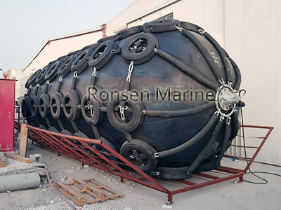
Pneumatic Rubber Fender
Last updated: 28 October 2026 · Reading time: 14 min · Author: [Jack], Marine Fender Engineer, 12 years specifying fender systems for ports, terminals and vessel owners · Applicable standards: ISO 17357-1:2014 Ships and marine technology — Pneumatic rubber fenders — Part 1: High-pressure; ISO 17357-2 (foam-filled); OCIMF Mooring Equipment Guidelines (MEG4); PIANC 2024 Marine Fenders: Recommendations for Design, Procurement and Installation
If you searched this phrase, you are probably either specifying fenders for a berth or a ship-to-ship operation, or comparing pneumatic fenders with foam-filled and solid rubber types. This guide explains what a pneumatic rubber fender is, how it works, the difference between 50 kPa and 80 kPa types, how to size one correctly, and how to tell a compliant product from a non-compliant one. No marketing claims — just the engineering.
What this guide covers
- Definition and working principle
- Not to be confused with: ship launching airbags
- Construction: what is inside a pneumatic fender
- 50 kPa vs 80 kPa — the standard defines two types
- Performance: initial pressure, reaction force and deflection
- Sizing by berthing energy (with worked example)
- Pneumatic vs foam-filled vs solid rubber
- Installation, inflation and inspection
- How to verify ISO 17357-1 compliance
- Common mistakes
- Frequently asked questions
1. Definition and working principle
A pneumatic rubber fender is a hollow, air-filled marine fender made of reinforced rubber, designed to absorb a vessel’s berthing energy by compressing the air inside. As the fender deflects, the internal air pressure rises and the fender pushes back against the vessel. When the vessel moves away, the air expands and the fender returns to shape.
The principle is simple: the air does the work. That is why pneumatic fenders typically deliver more energy absorption per unit size and lower reaction force than solid rubber fenders of the same dimensions.
Two features define the product:
-

Pneumatic Fender
Initial internal pressure — the pressure before any load is applied. This sets the fender’s stiffness and reaction curve.
- Reinforced rubber body — typically multiple layers of rubber and cord (tyre-cord or synthetic fibre) built up on a mandrel, finished with end flanges and a safety valve.
2. Not to be confused with: ship launching airbags
This is the most common source of specification errors. Pneumatic rubber fenders and ship launching airbags are different products, built to different standards, for different purposes.
| Feature | Pneumatic rubber fender | Ship launching airbag |
| Purpose | Absorb berthing energy | Support and move vessels during launch or docking |
| Standard | ISO 17357-1(high-pressure pneumatic) | GB/T 41888-2022 (launching procedure) |
| Working principle | Air compression absorbs energy | Roller-like movement under load |
| Typical pressure | 50 kPa or 80 kPa initial | Up to ~0.12 MPa or more |
| Safety device | Pressure relief valve | None (controlled by release brake) |
| Use location | Quay face, dolphin, ship-to-ship | Slipway, dock, heavy lifting |
A launching airbag must never be used as a fender, and a fender must never be used as a launching airbag. Their designs, reinforcement patterns and failure modes are different. Specifiers who source from the same factory for both products should insist on separate type-test reports for each.
3. Construction: what is inside a pneumatic fender
From outside in:
- Outer rubber cover — abrasion, weather and seawater resistant. Thickness and formulation vary by manufacturer and by the severity class specified.
- Reinforcement layers (cord plies) — the load-bearing structure. The number and type of plies determine the burst margin. Ask for the ply detail in the datasheet.
- Inner liner — air-tight layer that retains pressure.
- End flanges and chain tyre net — steel flanges carry the mounting loads; many designs add a chain-and-tyre net for extra protection in ship-to-ship and heavy-duty use.
- Safety valve — mandatory on pneumatic fenders. Set below the burst pressure and above the maximum working pressure.
- Inflation valve and pressure gauge — for filling and routine checks.
The performance of a pneumatic fender depends on cord layout, rubber compound, and manufacturing quality — not on diameter alone. Two fenders of the same diameter from different suppliers can have very different reaction forces and service lives.
4. 50 kPa vs 80 kPa — the standard defines two types
ISO 17357-1:2014 defines pneumatic rubber fenders by their initial pressure:
| Type | Initial pressure | Characteristics | Typical application |
| 50 kPa type | 50 kPa | Lower reaction force, higher deflection, softer | General berthing, ship-to-ship, terminals with sensitive structures |
| 80 kPa type | 80 kPa | Higher stiffness, higher energy capacity for the size, higher reaction | Heavy berths, large vessels, where space is limited |
Key point: The standard requires that the fender be tested at its rated initial pressure. A 50 kPa fender tested at 80 kPa will not perform to its published curve, and vice versa. Always confirm which type you are buying and which pressure the performance curve was measured at.
ISO 17357-1 was reaffirmed in 2024 with no technical changes, so references to the 2014 edition remain valid. Some national standards (for example China’s GB/T 21482-2008) have since been withdrawn and replaced by references to ISO 17357-1. Do not accept a quotation that cites a withdrawn standard.
5. Performance: initial pressure, reaction force and deflection
Pneumatic fenders are specified by three linked parameters:
- Energy absorption (GJ or kJ) — the kinetic energy the fender can absorb at its design deflection.
- Reaction force (kN) — the force the fender exerts on the vessel and structure at that deflection.
- Deflection (%) — normally ≤60% for pneumatic fenders at rated energy. Beyond this, the reaction force rises sharply.
The published performance figures are measured at the rated initial pressure and at a specified deflection. Two numbers to always ask for together:
- Energy absorption at what deflection?
- Reaction force at that same deflection?
A note on performance claims: Some suppliers publish an energy figure measured at 60% deflection and a reaction figure measured at 50%, then combine them in one brochure line. That number is not usable for design. Ask for the full force-deflection curve and the energy-deflection curve, both from a type test to ISO 17357-1.
Inflation matters. Under-inflation makes the fender too soft and increases deflection beyond design, risking damage. Over-inflation raises reaction force and can exceed the safety valve setting. Check pressure with a calibrated gauge before each operation, and keep a log.
6. How to size a pneumatic fender — the calculation
The correct method is energy-based, not diameter-based.
Step 1 — Calculate berthing energy
For normal berthing, the kinetic energy is:
E = ½ · M · V² · Cₑ · Cₘ · Cₛ
Where:
M = effective mass of the vessel (displacement × virtual mass factor, often 1.1–1.3)
V = berthing velocity (m/s) — from OCIMF or port design code
Cₑ = eccentricity factor (how far the contact point is from the centre of gravity)
Cₘ = virtual mass factor
Cₛ = softness factor (accounts for fender deflection and hull flexibility)
Step 2 — Select type and size
Choose a pneumatic fender whose rated energy ≥ E at ≤60% deflection, and whose reaction force at that deflection ≤ the allowable load of the fender panel, dolphin, bollard and vessel hull. Decide between 50 kPa and 80 kPa based on the required reaction force and available space.
Step 3 — Check deflection and clearance
Confirm that at the design energy, the fender deflects within the manufacturer’s design range and the vessel does not strike the structure behind the fender.
Step 4 — Check spacing and number
Space fenders so the vessel’s hull is supported along its length. For ship-to-ship operations, use the OCIMF guidance on fender placement and hawser loads.
Worked example — 8,000 t vessel, 0.12 m/s berthing velocity:
Assuming M = 8,800 t (including virtual mass), Cₑ = 0.8, Cₘ = 1.2, Cₛ = 0.9:
E = 0.5 × 8,800,000 × 0.12² × 0.8 × 1.2 × 0.9 ≈ 433 kJ
Select a pneumatic fender rated ≥ 433 kJ at ≤60% deflection, 50 kPa or 80 kPa as required, with reaction force within the structure’s allowable load. Always confirm the selection against the manufacturer’s tested performance curve.
7. Pneumatic vs foam-filled vs solid rubber
| terion | Pneumatic (ISO 1735-1) | Foam filled (ISO 17357-2) | Solid rubber |
| Working principle | Air compression | Foam compression | Rubber shear/compression |
| Puncture consequence | Pressure loss, needs repair | Performance retained | Unaffected |
| Energy absorption per size | Very high | High | Moderate |
| Reaction force | Low, very predictable | Moderate, predictable | Higher |
| Weight | Light to moderate | Heavy | Heavy |
| Maintenance | Valve, pressure, cord checks | Visual and deflection checks | Very low |
| Best for | Ship-to-ship, temporary berths, low reaction | High-traffic, exposed, heavy berths | Small craft, fixed structures |
Rule of thumb: Choose pneumatic when low reaction force and light weight matter — ship-to-ship transfer, temporary berths, and where the dock structure cannot take high loads. Choose foam-filled when the berth cannot tolerate a sudden fender failure, such as high-traffic or exposed locations. Choose solid rubber for small craft and low-energy berths.
On this site: see our guide to foam filled fenders for the foam comparison, and how to position ship launching airbags for launching equipment — a different product family.
8. Installation, inflation and inspection
Installation
- Align the fender so the load transfers through the end flanges to the support structure. Misalignment causes cord damage.
- Use the correct grade and torque for mounting bolts; check against the manufacturer’s drawing.
- For fenders with a chain tyre net, confirm the net is correctly seated and the shackles are secured.
- For ship-to-ship, follow OCIMF MEG4 guidance on fender positioning and line tension.
Inflation
- Inflate to the rated initial pressure only (50 kPa or 80 kPa as marked). Use a calibrated gauge.
- Never exceed the safety valve setting. The safety valve must be functional and accessible.
- Allow the fender to settle, then re-check pressure before use.
Inspection (per PIANC 2024 and OCIMF guidance)
- Daily or pre-use: visual check for cuts, bulges, cord exposure and chain wear.
- Check inflation pressure with a calibrated gauge; log the reading.
- Check the safety valve annually and after any over-pressure event.
- Check mounting bolts, flanges and welds for movement or corrosion.
- After any hard berthing, inspect immediately — internal cord damage is not always visible externally.
- Retain the type-test report and inspection log on file.
9. How to verify ISO 17357-1 compliance
Before purchase, ask the supplier for:
- Type-test report to ISO 17357-1:2014, including force-deflection and energy-deflection curves, burst test, and compression set.
- Rated initial pressure clearly stated as 50 kPa or 80 kPa, matching the performance curve.
- Cord ply detail — number, type and layout.
- Safety valve setting and certificate.
- Factory audit or accreditation — ISO 9001 at minimum; some ports require additional third-party inspection.
- Traceability — each fender should carry a serial number and data plate linking it to the test report.
Red flags:
- No type-test report, or a report that does not match the quoted model.
- Performance figures with no deflection stated.
- Datasheet cites a withdrawn national standard.
- “We comply with ISO 17357” with no test documentation offered.
10. Common mistakes
- Sizing by diameter — ignoring energy, reaction force and deflection.
- Confusing 50 kPa and 80 kPa — using the wrong curve invalidates the design.
- Comparing brochure numbers at different deflections — always ask for the curve.
- Using a launching airbag as a fender — different product, different failure mode.
- Ignoring the support structure — a fender that overruns its allowable reaction damages the dock.
- Skipping pressure checks — under- or over-inflation changes performance and shortens life.
- Buying on price alone — the cheapest fender is the one that fails during a ship-to-ship transfer and closes an operation.
- Assuming “rubber fender” covers all types — pneumatic, foam-filled and solid rubber are three distinct product families.
11. Frequently asked questions
What is a pneumatic rubber fender?
A hollow, air-filled fender made of reinforced rubber that absorbs berthing energy by compressing the air inside. It is specified in ISO 17357-1.
What is the difference between 50 kPa and 80 kPa pneumatic fenders?
They are the two types defined by ISO 17357-1. 50 kPa fenders are softer with lower reaction force; 80 kPa fenders are stiffer with higher energy capacity for the same size.
Are pneumatic fenders the same as foam filled fenders?
No. Pneumatic fenders use compressed air; foam filled fenders use closed-cell foam. They are covered by different standards (ISO 17357-1 vs ISO 17357-2) and suit different applications.
What standard applies to pneumatic rubber fenders?
ISO 17357-1:2014, reaffirmed in 2024. OCIMF MEG4 and PIANC 2024 provide complementary guidance on system design and mooring.
How long do pneumatic rubber fenders last?
With correct specification, inflation and inspection, 8–15 years is normal. Cord life and rubber ageing depend on UV, abrasion and pressure cycles; the safety valve and inflation system need regular checks.
Can a pneumatic fender be repaired?
Yes — minor skin damage can often be patched, and cord damage can sometimes be repaired by the manufacturer. Any repair must be followed by a pressure test. A fender that has burst or shown cord exposure should be withdrawn.
Is a pneumatic fender the same as a ship launching airbag?
No. They are different products for different purposes, built to different standards. See Section 2 above.
About the author
[Jack], [credentials], lead fender engineer at [Ronsen Marine]. 12 years specifying fender systems for container terminals, bulk ports, tug operators, ship-to-ship operations and offshore facilities. Contact: [sales@ronsen-marine.com] · +[86 183 5328 0885]
