

How Do Yokohama Pneumatic Fenders Work?
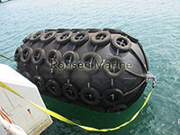
Yokohama Pneumatic Fenders
Quick answer: A Yokohama pneumatic fender works as a sealed, air-spring shock absorber. Its reinforced-rubber body is filled with compressed air at 50 kPa (P50) or 80 kPa (P80). When a hull presses against it, the trapped air compresses and the rubber body deforms, converting the vessel’s kinetic berthing energy into pressure and elastic strain. Because air is highly compressible, the reaction force rises gently — so the hull and berth receive a soft, controlled load instead of a hard impact. Remove the load and the fender rebounds to its original shape.
First, a terminology note that matters commercially. “Yokohama” is the brand name of The Yokohama Rubber Co., which pioneered the design in the 1950s . In procurement, it’s now used descriptively for any ISO 17357-compliant pneumatic fender — so “Yokohama fender,” “Yokohama-type fender,” and “pneumatic rubber fender” refer to the same technical category . When you buy one, the brand name alone is not a specification; ISO 17357-1:2014 compliance plus classification-society approval is .
The Physics in Plain Terms
A pneumatic fender works for one fundamental reason: air is compressible, rubber is not the spring — the air is.
The kinetic energy of an approaching vessel is:
E = ½ Mₑ V² × Cₑ × C_m × C_s × C_c
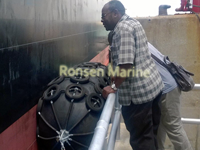
Pneumatic Yokohama Fenders
…the PIANC berthing-energy equation, where Mₑ is virtual mass and V is approach velocity . That energy has to go somewhere. A solid rubber fender dissipates it through material stiffness — which fights back hard. A pneumatic fender dissipates it by shortening the internal air column, so pressure rises progressively and the force-deflection curve stays shallow through most of the travel .
This is the core advantage, and it has four consequences:
- High energy absorption with low reaction force. A Ø3300×6500 mm unit absorbs 1814 kNm (P50) while returning only 3015 kN — and 2532 kNm / 3961 kN at P80 .
- Hull pressure stays within class-society limits. Typical hull pressure at 60% deflection runs 128–195 kPa depending on size and pressure class .
- Self-floating and tidal. The air charge provides buoyancy, so the fender rides the waterline as tide and vessel movement change — no adjustable brackets .
- Full elastic recovery. Once the vessel retreats, compressed air re-expands and the body returns to shape. No break-in cycle, unlike solid rubber .
The Yokohama manufacturer’s own force-deflection comparison shows pneumatic fenders return lower reaction force and lower hull pressure than solid fenders at buckling, normal deflection, and abnormal-berthing points .
Internal Structure: 4 Engineered Layers
| Layer | Material |
| Outer rubber | Wear-compound rubber |
| Reinforcement | Synthetic tire-cord plies at opposing angles |
| Inner rubber | Air-tight membrane |
| End flanges + valves | Steel, with inlet and relief valve |
Why this layering matters: The cord angle and flange design are pressure-class-specific. This is the reason behind a critical safety rule — never inflate a P50 body to P80 pressure . The cord angle, end-ring geometry, and safety factors differ between classes.
P50 vs. P80: Same Size, Different Performance
Initial pressure is fixed at the design and order stage — you don’t tune it on-site . Raising pressure from 50 to 80 kPa increases energy absorption by roughly 35–40%, but pushes proportionally more reaction force back to the hull and berth structure .
| Initial pressure | Energy absorption | Reaction force | Typical use |
| 50 kPa (P50 | Baseline (9GEA) | Lowest | LNG, aluminium hulls, yachts, naval, mid-size STS |
| 80 kPa (P80) | ~`1.3-1.5 x P50 | Higher | VLCC/LNG, high-energy berthing, limited fender count |
Real spec-table values confirm the pattern. For a Ø2500×5500 mm fender: P50 = 943 kNm / 2019 kN; P80 = 1317 kNm / 2653 kN. For Ø2000×3500 mm: P50 = 308 kNm / 875 kN; P80 = 430 kNm / 1150 kN .
Selection rule: sensitive hull → P50. Heavy tanker STS with high approach speed → P80. Then verify the hull can actually accept the higher hull pressure.
Types: Net (Type I) vs. Sling (Type II) vs. Hydro-Pneumatic
Type I — Net type. A chain-tire-net or wire/fibre net wraps the body (chain plus used tires, often with rubber sleeves to protect the hull) . Highest abrasion life. Best for heavy STS, tankers, LNG, and permanent berths .
Type II — Sling type. No hard net; thick outer rubber with integral slings or lifting eyes . Lighter, quick to deploy, available in non-marking options. Suited to yachts, naval, and cruise hulls .
Hydro-pneumatic. Part air, part water ballast (~60–70% water) for submerged low-freeboard contact — submarines and special low-hull-pressure operations .
Standard Sizes and Performance (ISO 17357-1:2014)
The standard range runs from Ø500×L1000 mm to Ø4500×L12000 mm, with sizes commonly stocked and delivered worldwide . All figures below are at 60% deflection; tolerance is typically ±10% .
| Size (DxL,mm) | P50 GEA (kNm) | P50 Reaction (kN) | P80 GEA (kNm) | P80 Reaction (kN) |
| 1000 x 1500 | 32 | 182 | 45 | 239 |
| 1500 x 3000 | 153 | 579 | 214 | 761 |
| 2000 x 3500 | 308 | 875 | 430 | 1150 |
| 2500 x 5500 | 943 | 2019 | 1317 | 2653 |
| 3300 x 6500 | 1814 | 3015 | 2532 | 3961 |
| 4500 x 12000 | 6473 | 7984 | 9037 | 10490 |
Note on units: some catalogs label the energy column “kJ,” others “kNm” or “KNm.” In this context they describe the same guaranteed energy absorption value. Use your supplier’s curve for final design — and remember GEA is the integral of reaction force over deflection to 60%, measured at ≤80 mm/min under the ISO parallel-compression test .
Where They’re Used
Ship-to-ship oil and LNG transfer; ship-to-dock berthing; oil terminals and VLCC/ULCC berths; FPSO and FSU offloading; offshore wind and supply vessels; cruise terminals; naval and submarine berthing; floating docks and marinas; emergency and lay-by protection .
The Yokohama historical record is worth knowing: the 1950s breakthrough came when engineers realized that pressurizing air inside a rubber shell delivered superior absorption while slashing material cost and weight. A single 3.3 m × 6.5 m solid rubber fender would have required over 70 cubic metres of rubber .
How to Select the Right Fender
- Calculate berthing energy using the PIANC equation — displacement, approach velocity, berthing coefficients .
- Set the allowable hull pressure limit — LNG, cruise, and naval hulls need the lowest values .
- Match GEA at 60% deflection to the calculated energy with margin .
- Choose P50 or P80 by hull sensitivity .
- Choose net or sling by abrasion duty and marking risk .
- Verify certification — ISO 17357-1:2014, with ABS/BV/DNV/CCS/LR class approval on request .
- Check the markings — ISO part, size, pressure rating, and serial number .
Installation and Maintenance
- Inflate with dry air or nitrogen to the rated pressure .
- Test the safety relief valve before deployment. Standard setting is 175 kPa for P50 (Ø2500×4000 mm and larger), 230 kPa for P80 .
- Check pressure monthly — sunlight and temperature can shift readings .
- Wash with fresh water after seawater exposure; inspect for cuts over 1 cm, exposed cord, and net corrosion .
- Store deflated, shaded, away from ozone sources and sharp objects. Never overinflate .
- Pressure drops over time due to permeation through the rubber — routine checks prevent under-inflation .
With correct care, quality pneumatic fenders typically last 6–10 years, and net-type units in moderate service can exceed 10 years .
Frequently Asked Questions
How does a Yokohama pneumatic fender absorb impact energy?
It compresses the trapped air inside its sealed, reinforced-rubber body. Kinetic berthing energy becomes increased internal air pressure plus elastic strain in the cord layers. The pressure rises progressively, so reaction force stays low, and the fender rebounds when the load is removed .
Why is it called a Yokohama fender?
Because The Yokohama Rubber Co. developed the original air-filled marine fender in the 1950s. “Yokohama type” now describes ISO-style pneumatic rubber fenders from any qualified manufacturer .
What pressure should a pneumatic rubber fender be inflated to?
Normally 50 kPa (P50) or 80 kPa (P80) at 20°C — fixed by design, never mixed between classes .
What is the difference between a pneumatic fender and a foam fender?
A pneumatic fender uses compressed air and can be deflated for transport and repair; a foam fender uses closed-cell foam and cannot deflate or be pressure-tuned .
What is the safety valve setting on a Yokohama pneumatic fender?
175 kPa for P50 units of Ø2500×4000 mm and larger; 230 kPa for P80 .
How long does a pneumatic fender last?
Typically 6–10 years with proper maintenance; net types in moderate service can exceed 10 years .
Key Takeaways
A Yokohama pneumatic fender is an air spring, not a rubber bumper: the compressible air does the energy absorption, while the reinforced-rubber body contains pressure and distributes the load. Size it by GEA at 60% deflection, rate it by its pressure class (P50 or P80), and never swap those classes — the cord angle and end-ring safety factors are different. For low hull-pressure operations, choose P50; for high-energy tanker STS, choose P80 and confirm the hull can accept the reaction force.
