

Ship Launching Airbags | Heavy-Duty Marine Rubber Airbags for Vessel Launching

Marine Airbag-RONSEN MARINE
ISO 14409:2011 certified marine rubber airbags (also called pneumatic rollers) for ship launching, vessel retrieval, heavy lifting and marine salvage. Diameter 0.8-2.5 m, effective length 6-25 m, 4-12 cord layers, working pressure 0.05-0.24 MPa. Request a quote.
What Are Ship Launching Airbags?
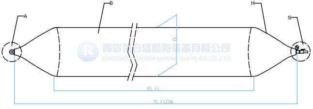
A ship launching airbag is a cylindrical, cord-reinforced rubber tube with tapered ends that is inflated with compressed air to support, lift and move a vessel along a slipway. The body is built from three functional layers: an inner rubber layer that seals air and resists seawater; synthetic tire-cord reinforcement layers (nylon 6 or polyester, 1400dtex/3) that carry the hoop stress; and an outer rubber layer that protects against abrasion, UV and impact during rolling. Also known as marine rubber airbags, rubber airbags, pneumatic rollers or ship launching balloons, they replace fixed concrete slipways at thousands of shipyards worldwide.
Ship Launching Airbag ISO 14409
The technology is based on the traditional log-rolling method. Once the keel blocks are removed, the vessel rests on deflated airbags; calibrated compressors inflate them to the target working pressure, and the hull rolls down a 1:70 to 1:10 inclined way at 0.5-1 m/s before floating free. A single set can launch vessels from a few tens of tons to over 10,000 tons, depending on specification and quantity.

Ship Launching Airbags: Key Specifications
The table below is the reference buyers use to shortlist a size. Exact rated working pressure, burst pressure and bearing capacity must be confirmed against the certification package for the ordered ply rating and diameter.
| Parameter | Standard range / value | Notes |
| Diameter (D) | 0.8 – 2.5 m (up to 3.0 m custom) | Common stock: 1.0 / 1.2 / 1.5 / 1.8 / 2.0 m |
| Effective length (EL) | 6 – 25 m | Cylindrical contact length; excludes tapered ends |
| Total len
gth (TL) |
7 – 28 m | EL plus two conical end caps and end fittings |
| Cord layers (plies) | 4, 5, 6, 7, 8, 9, 10 (12 on request) | More layers = higher burst pressure |
| Working pressure | 0.05 – 0.24 MPa | Set by diameter and ply rating; never exceed it |
| Burst safety factor | Min. 3:1 (ISO 14409); premium 4.5:1 | Burst pressure / working pressure |
| Service life | 80 – 200 launch cycles | With rinse, dry and covered storage |
| Standard | ISO 14409:2011, CB/T 3795, ISO 17682:2013 | Mill test + hydrostatic burst report |
| Reuse / mobility | Deflate, roll up, transport to next site | No permanent civil works required |
Construction and Material Quality
The outer rubber layer protects the cord plies from abrasion and hard use, with enough tensile and tear strength for outdoor, saltwater conditions. The reinforcement uses synthetic tire-cord fabric in a 3-strand configuration; each cord has a minimum breaking strength of 31 kgf, and each layer contributes roughly 310 N per cord. The inner rubber layer is formulated for airtightness and seawater resistance. End fittings are steel (Q355 / SS304 / SS316), with inlet valve, pipe fitting and seal end ring supplied as standard accessories.
Rubber compound is independently tested to the values below. A mill test certificate and hydrostatic burst test report (video evidence on request) are issued with every shipment.
| Test item | Required value | Method |
| Tensile strength | >= 18 MPa | ISO 37 |
| Elongation at break | >= 400% | ISO 37 |
| Hardness (Shore A) | 60 +/- 10 | ISO 7619-1 |
| Tear strength | >= 400 N/cm | ISO 34-1 |
| Compression set, 70 C / 22 h | <= 30% | ISO 815-1 |
| Thermal ageing retention, 70 C / 96 h | >= 80% | ISO 188 |
| Static ozone ageing, 40 C / 96 h | No crack | ISO 1431-1 |
How to Calculate the Number of Airbags You Need
Airbag quantity is not a catalogue guess – it is an engineering calculation. The simplified approach used by shipyards is:
- Step 1: determine total hull weight (lightship + outfitting margin + water trapped in the hull).
- Step 2: estimate contact area. Contact width is approximately diameter x 0.6 (empirical deformation factor); total contact length is the sum of the effective lengths of all airbags placed.
- Step 3: single airbag load capacity = working pressure x contact width x effective length x safety derating (0.7-0.8). Required count = total vessel weight / single airbag load capacity.
Worked example – 500-ton barge, 1.5 m diameter, 12 m effective length, 0.10 MPa working pressure: contact width is about 0.9 m, so one bag carries roughly 0.10 x 0.9 x 12 x 0.75 = 81 kN, or about 8.3 tons. Required count is approximately 500 / 8.3 = 60 airbags, distributed along the keel and bilge. Always add a 15-20% buffer: slope irregularities, uneven inflation and tidal timing are variables you cannot fully control on launch day. Tell us the vessel weight, hull lines and slipway gradient and we will return a layout drawing and a firm quantity.
How the Airbag Launching Process Works
- Block removal – wooden or steel support blocks under the hull are removed, leaving the vessel resting on deflated airbags placed transversely.
- Inflation – compressors fill the airbags to target pressure, monitored by calibrated gauges (recertified within 12 months).
- Rolling – the vessel moves down the inclined way as airbags deform and rotate beneath the hull, advancing and reinflating the leading bags.
- Water entry – the hull floats free; airbags are recovered, deflated and stored for reuse.
The ramp must be cleaned of nails, stones and sharp burrs (especially around the A-bracket and stern post), levelled to less than 80 mm cross-slope error, and extended far enough into the water. Ramp bearing capacity should be at least twice the working pressure of the airbags. A slow-veer winch (about 9-13 m/min) holds the vessel; ship speed must not exceed 6 m/min, and the vessel must not touch the ground even at the airbags’ lowest working height.
Airbag Launching vs Concrete Slipway: Cost and Site Comparison
| Factor | Airbag launching | Concrete slipway |
| Capital cost | 60-80% lower for vessels under 5,000 t | High civil engineering investment |
| Site | Graded beach, compacted soil, temporary ramp | Fixed, permanent infrastructure |
| Mobilisation | Portable – moved to repair sites | None; built in place |
| Flexibility | One set reused 80-200 cycles | Single dedicated slope |
| When to avoid | Wind > Beaufort 6, cross-slope > 80 mm | Long lead time and high spend |
Applications of Marine Rubber Airbags
- Ship launching and landing – barges, tugboats, cargo ships, workboats and yachts.
- Vessel retrieval and drydocking when no fixed dock is available.
- Heavy lifting and moving – bridge caissons, prefabricated modules, floating docks.
- Marine salvage and refloating of stranded or sunken vessels.
- Buoyancy aid for underwater installation works.
Common Failure Modes and How to Avoid Them
| Failure mode | Cause | Prevention |
| Burst under dynamic load | Under-specified ply count | Engineer ply rating to vessel weight |
| Hull plate overstress | Airbags spaced too far apart | Follow the calculated layout drawing |
| Puncture of outer rubber | Sharp objects on the slipway | Clear and level the ramp; grind all burrs |
| Silent leak during launch | No pressure-hold test | Inflate to 1.1x WP, hold 30 min, drop <5% |
| Cord failure | Overinflation for a faster lift | Never exceed rated working pressure |
Pre-Launch Inspection Checklist
- Visual inspection – no cuts longer than 50 mm, no cord exposure.
- Pressure hold test – inflate to 1.1x working pressure, hold 30 min, pressure drop below 5%.
- Relief valve calibrated and installed on every compressor.
- Pressure gauges certified within the last 12 months and visible to the controller at all times.
- Slope gradient verified by a surveyor; cross-slope error within 80 mm.
- Tide, wind and weather forecast checked – stop work above Beaufort 6.
- Recovery boat and crew on standby; emergency-stop drill briefed to all personnel.
Certificates and Documentation Importers Should Ask For
- Mill test certificate for the rubber compound.
- Hydrostatic burst test report, with video evidence preferred.
- Third-party inspection to CCS, BV, ABS, DNV, LR, GL, NK, KR, RINA or RMRS as required by the flag state.
- Traceability code on each airbag body, matched to the test report.
- Repair kit (repair rubber, repair machine and heating plate) supplied free of charge during the warranty period.
Frequently Asked Questions
Q: How many times can a ship launching airbag be reused? A: 80-200 cycles with proper rinsing, drying and storage. Inspect the bag after every 10 launches.
Q: Can airbags launch a 10,000-ton ship? A: Yes – with enough bags, the correct ply count and an engineered spacing layout. It is never done with one or two bags.
Q: What pressure do marine rubber airbags use? A: Typically 0.05-0.24 MPa depending on diameter and ply rating. The value is always below the rated working pressure shown on the load chart.
Q: Are launching airbags the same as pneumatic fenders? A: No. Fenders absorb impact energy; launching airbags carry quasi-static hull weight and roll. They differ in cord angle, standard and end fitting.
Q: What is the difference between Effective Length and Total Length? A: Effective length is the cylindrical body that provides the actual contact surface and load-bearing capacity. Total length includes the two conical ends and metal terminal fittings.
Q: How long is the warranty? A: Warranty periods range from 12 to 36 months depending on the supplier and ply specification; free repair material is provided during the warranty period.
Request a Quote and Layout Proposal
Send us the vessel weight, hull length and beam, slipway gradient, and target launch date, and we will return a written proposal with airbag size, ply rating, quantity, layout drawing, certification package, unit price, lead time and incoterms. Minimum order quantity is one set; OEM and custom sizes are accepted.
Related Products