

Floating Yokohama Pneumatic Rubber Fenders: ISO 17357-1:2014 P50 & P80 for STS and Ship-to-Quay
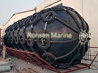
Floating Yokohama Pneumatic Rubber Fenders
ISO 17357-1:2014 | P50 / P80 | Net-Type & Sling-Type | Ship-to-Ship & Ship-to-Quay
Ronsen Marine supplies floating Yokohama pneumatic rubber fenders in nominal sizes from D500 × L1000 mm to D4500 × L12000 mm, inflated to 50 kPa (P50) or 80 kPa (P80) initial internal pressure. Every unit is built to the energy-absorption and reaction-force requirements of ISO 17357-1:2014, fitted with a galvanised chain-and-tyre-net or supplied as a sling-type unit, and delivered with type-test records and classification-society documents on request. Use this page to size your fender line, compare P50 with P80, and request a berthing-energy calculation.
What Is a Floating Yokohama Pneumatic Rubber Fender?
A floating Yokohama pneumatic rubber fender — often written as Yokohama fender, pneumatic rubber fender or simply pneumatic fender — is a cylindrical, air-filled marine buffer. It is made of an inner rubber layer, multiple plies of high-tensile synthetic tyre cord, and an outer rubber cover, then vulcanised into a single seamless body. The fender floats at the waterline under its own buoyancy and is hung alongside a vessel or a quay wall by chains, slings or wire rope.
When a hull presses against it, the trapped air compresses and the cord-reinforced rubber deforms elastically. The vessel’s kinetic energy is converted into air pressure and controlled rubber deflection instead of being transmitted into the hull plating or the berth structure. On rebound the air re-expands and the fender returns to shape, ready for the next impact.
The name comes from the original commercial design introduced by The Yokohama Rubber Co. in the 1950s. Today “Yokohama-type” is the generic industry term for this class of floating pneumatic fender, and performance is governed by ISO 17357-1:2014 rather than by any single brand.
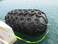
Floating Pneumatic Rubber Fenders
Why buyers specify pneumatic instead of foam-filled
- Reaction force is the lowest of all floating fender types at the same energy rating — critical for aluminium hulls, LNG carriers and older berth structures.
- Performance is adjustable: raise internal pressure from 50 kPa to 80 kPa and absorption rises by roughly 40%, or drop pressure to soften the push-back on a sensitive hull.
- Air-filled units can be deflated, folded and shipped in a standard container; one 40-foot container carries far more deflated fenders than solid foam equivalents.
- On-site repair is possible. Punctures, end-flange damage and valve faults are patchable; a foam fender must be replaced.
- The fender follows the tide. Self-floating installation needs no adjustable frame, which is why pneumatic units dominate locations with large tidal ranges.
Construction: Four Layers, One Seamless Body
Understanding the layer stack is the fastest way to judge a supplier’s quality. Each layer has a single job, and a cheap fender is usually cheap because one of these jobs was cut short.
| Layer | Function | What to Check on Delivery |
| Inner rubber layer | Air-tightness and pressure transfer; protects the cord from the air charge | No thin spots at the valve neck; pressure hold test recorded |
| Synthetic tyre-cord plies | Carries membrane stress and holds geometry under compression | Ply count and cord angle per the type test; ≥2 plies on standard sizes |
| Rubber matrix between plies | Bonds the reinforcement and distributes shear load | No ply separation after the hammer or compression test |
| Outer rubber cover | Abrasion, tear, UV and chemical resistance; the only layer the water sees | Shore hardness, abrasion value and ozone-crack test on the mill sheet |
Two construction details decide whether a fender survives its first bad day.
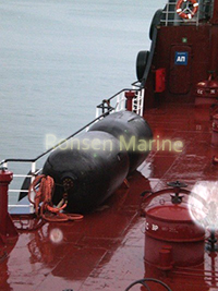
Sling Floating Yokohama Pneumatic Fenders
End flanges. The flange is where the chain, sling and towing ring concentrate their load into the rubber body. Look for a heavy-duty internal flange system with a steel insertion plate fully encapsulated in rubber, not a thin ring bonded to the end face. A failed flange pulls the chain through the end of the fender — the most common catastrophic failure mode in STS work.
The safety valve. ISO 17357-1:2014 requires a pressure relief valve on fenders of 2500 mm diameter and above. The valve opens automatically when accidental over-compression drives internal pressure above the set point, then re-seats. Smaller diameters can be fitted with a valve on request — recommended for any fender working in a fixed quay location where operators cannot see the pressure gauge.
Performance Tables (ISO 17357-1:2014, 60% Deflection)
All values below are Guaranteed Energy Absorption (GEA), reaction force and hull pressure at 60% deflection, measured at 20°C with clean dry air. They comply with the requirements of ISO 17357-1:2014. Body weight varies ±10% and reaction force ±10%. Figures for special sizes are available on request.
P50 — Initial internal pressure 50 kPa
| Size D × L (mm) | GEA (kNm) | Reaction Force (kN) | Hull Pressure (kN/m²) |
| 500 × 1000 | 6 | 64 | 132 |
| 600 × 1000 | 8 | 74 | 126 |
| 700 × 1500 | 17 | 137 | 135 |
| 1000 × 1500 | 32 | 182 | 122 |
| 1000 × 2000 | 45 | 257 | 132 |
| 1200 × 2000 | 63 | 297 | 126 |
| 1350 × 2500 | 102 | 427 | 130 |
| 1500 × 3000 | 153 | 579 | 132 |
| 1700 × 3000 | 191 | 639 | 128 |
| 2000 × 3500 | 308 | 875 | 128 |
| 2500 × 4000 | 663 | 1381 | 137 |
| 2500 × 5500 | 943 | 2019 | 148 |
| 3300 × 4500 | 1175 | 1884 | 130 |
| 3300 × 6500 | 1814 | 3015 | 146 |
| 3300 × 10600 | 3067 | 5257 | 158 |
| 4500 × 9000 | 4752 | 5747 | 146 |
| 4500 × 12000 | 6473 | 7984 | 154 |
P80 — Initial internal pressure 80 kPa
| Size D × L (mm) | GEA (kNm) | Reaction Force (kN) | Hull Pressure (kN/m²) |
| 500 × 1000 | 8 | 85 | 174 |
| 600 × 1000 | 11 | 98 | 166 |
| 700 × 1500 | 24 | 180 | 177 |
| 1000 × 1500 | 45 | 239 | 160 |
| 1000 × 2000 | 63 | 338 | 174 |
| 1200 × 2000 | 88 | 390 | 166 |
| 1350 × 2500 | 142 | 561 | 170 |
| 1500 × 3000 | 214 | 761 | 174 |
| 1700 × 3000 | 267 | 840 | 168 |
| 2000 × 3500 | 430 | 1150 | 168 |
| 2500 × 4000 | 925 | 1815 | 180 |
| 2500 × 5500 | 1317 | 2653 | 195 |
| 3300 × 4500 | 1640 | 2476 | 171 |
| 3300 × 6500 | 2532 | 3961 | 191 |
| 3300 × 10600 | 4281 | 6907 | 208 |
| 4500 × 9000 | 6633 | 7551 | 192 |
| 4500 × 12000 | 9037 | 10490 | 202 |
Reading the three numbers correctly matters more than picking the biggest fender. GEA is the energy the fender absorbs with no permanent deformation. Reaction force is what pushes back on the hull and the mooring system — size the bollards and fender lines against this, not against GEA. Hull pressure is the contact pressure on the vessel’s side shell; keep it below the allowable hull pressure for the ship class you are serving, which is why P50 is often specified for thin-plated and aluminium vessels even when P80 would absorb more energy.
Type I Net-Type vs Type II Sling-Type
There are two standard configurations. Choosing the wrong one is a frequent and expensive mistake.
| Feature | Type I — Chain & Tyre Net (CTN) | Type II — Sling Type |
| Protection | Truck or aircraft tyres laced with horizontal and vertical galvanised chain | No net; double-layer outer cover plus an extra tyre-cord ply |
| Best for | Tankers, barges, STS transfer, debris-heavy water, permanent berths | Yachts, cruise ships, naval vessels, non-marking requirements |
| Hull contact | Rubber sleeves cover the chains so chain marks do not reach the hull | Smooth rubber surface, no chain marks at all |
| Weight | Heavier — net mass is a substantial part of total handling weight | Lightest handling weight; easier to lift and reposition |
| Damage mode | A worn tyre or chain link can be replaced in the field | Damage goes through the outer cover before it is visible |
| Minimum size | Generally not offered below D800 × L1200 | Available from the smallest catalogue size |
| Chain size guidance | 12.5 mm up to D1000; 16 mm at D1200–D1500; 22 mm at D1500; 28 mm at D2000; 32–50 mm on the largest units | No chain in the product; flange, shackle and swivel only |
Galvanising matters. The horizontal and vertical chains, the towing ring, the shackles and the swivel are all hot-dip galvanised; stainless steel is available for the towing ring, flange and swivel when the duty calls for it. Rubber sleeves on the chain runs are not optional — they are the only thing stopping chain wear on the hull paint.
How to Size a Pneumatic Fender Line
Fender selection starts with the ship’s kinetic energy, not with the ship’s length. Two vessels of identical length can need completely different fender lines because displacement and berthing velocity dominate the result.
The berthing-energy formula
E = ½ × (M × V²) × Ce × Cm × Cs × Cc
where M is vessel mass, V is berthing velocity, Ce is eccentricity, Cm is virtual mass, Cs is softness and Cc is contact loss. The full worked calculation is supplied free with every quotation — send displacement, beam, draft, berthing velocity, hull type and quay configuration.
Worked example 1 — Feeder container ship at a quay
- Vessel: 1800 TEU feeder, displacement 22,000 tonnes, beam 27.6 m, berthing velocity 0.12 m/s
- Quay: solid concrete caisson, one fender line of four units
- Result: design energy per fender 310 kNm; selected D2000 × L3500 P50, GEA 308 kNm at 60% deflection
- Check: reaction force 875 kN and hull pressure 128 kN/m² are both within the berth and hull allowances, so the line is accepted without upsizing
Worked example 2 — STS transfer, two Aframax tankers
- Configuration: two 105,000 dwt tankers, approach velocity 0.10 m/s, two fender lines of three units each
- Constraint: hull pressure must stay below 175 kN/m² because one vessel has a thin upper-side shell
- Selected: D1700 × L3000 P50, GEA 191 kNm, hull pressure 128 kN/m² — P80 would have pushed 168 kN/m² and was rejected on that ground alone
- Lesson: the higher-energy P80 was not the better choice; hull pressure, not GEA, was the limiting parameter
Rules of thumb that keep you out of trouble
- Do not size by vessel length. Two ships of the same length with different displacement need different lines.
- Do not default to P80. Use P50 wherever hull-pressure or berth-structure limits are tight.
- Check the tide range. A fender line placed too high leaves the hull unsupported at low water; place the line so the fender sits at the loaded-draft waterline across the full tidal range.
- Verify the safety valve on every unit 2500 mm and above before deployment, and record the check by serial number.
- Do not use sling type in heavy tanker STS service — the unprotected cover will not survive the contact frequency.
- Never mix ISO 17357-1 high-pressure and low-pressure products in the same line; the pressure drift changes the load share.
Applications
- Ship-to-ship transfer (STS) — the primary application. Fenders hang alongside the hull on mooring chains or fibre rope; this is where low reaction force protects two expensive hulls at once.
- Ship-to-quay and ship-to-berth — hung from the quay face by guy chains or ropes, absorbing berthing energy without loading the structure.
- Offshore platforms and FPSO side defence — floating units follow heave and tide better than fixed rubber.
- LNG, LPG and chemical tanker terminals — low hull pressure and non-marking sling-type options available.
- Bulk, coal, grain and container terminals — net-type units take the abrasion and debris.
- Fast ferries and aluminium-hulled vessels — P50 or sling type to keep reaction force and marking down.
- Temporary or emergency fendering and rapid-response deployment — deflated units travel in a fraction of the space.
- Stand-off fenders to realign a ship with shore facilities after initial contact.
Pressure Options, Inflation and Storage
Initial pressure is measured cold at 20°C and stated as 50 kPa (0.5 bar, 0.05 MPa, roughly 0.5 kg/cm²) or 80 kPa (0.8 bar, 0.08 MPa). P50 is the general-duty choice; P80 is for high-energy applications where the berth and hull can accept the higher reaction force. A third way to adjust performance is to vary internal pressure within the rated range — useful when a single fender must serve both a light vessel and a heavy one across a season.
Inflation and gas
- Use clean, dry air from a calibrated source. Moist air corrodes the inside of the end fittings and drives pressure drift.
- Nitrogen is preferred for long-term or tropical deployment because it carries no moisture and pressure stays stable.
- Measure pressure cold. A unit inflated and left in direct sun will read high; re-check at ambient temperature before judging it over- or under-inflated.
- Never exceed the rated pressure. Over-inflation is the principal cause of end-flange and cord-ply failure.
Deflation, transport and storage
- For transport or a different location, deflate fully and fold — a standard container takes a large number of deflated units.
- For long-term storage, deflate to roughly 50% of working pressure or fully; store cool, shaded and ventilated.
- Keep away from sharp objects and ozone sources — electric motors, welding sets and transformers all accelerate rubber cracking.
- Stack on wooden pallets, never on concrete or damp ground, and inspect every three months during storage.
- Clean with fresh water after salty or oily duty before storage.
Maintenance Schedule
Pneumatic fenders need attention; foam fenders do not. That is the trade-off for low reaction force and repairability. A monthly check takes one person about ten minutes per unit and prevents the failures that cost real money.
| Interval | Check | Action |
| Before every deployment | Pressure with a calibrated gauge | Inflate or bleed to the rated pressure at ambient temperature |
| Monthly (in service) | Outer rubber for cuts, abrasions and bulges | Patch minor damage with marine-grade rubber and cold-vulcanising compound |
| Monthly (in service) | Chain/tyre net and sling wear, rust, broken links | Replace individual tyres and links; do not wait for a full net failure |
| Before every deployment | Safety valve operation | Function-test and record by serial number; replace if it sticks open |
| Quarterly | End flanges, shackles, swivel and towing ring | Torque-check and dye-penetrant inspect the flange plate |
| Every 3 months (storage) | Pressure and storage condition | Re-inflate to 50%, inspect for ground contact and ozone cracking |
| Annually | Full record review | Trend the pressure-drift data; a steady drop points to a valve or cord-layer fault |
Manufacturing, Testing and Certification
Manufacturing follows a fixed sequence: inner-tube extrusion, cord-ply wrapping at the designed angle, outer-cover building, moulding and vulcanisation, flange and valve fitting, net or sling assembly, then testing. Every step is recorded against the fender’s serial number so a certificate can be matched to the physical unit years later.
Tests performed
- Air-tightness and pressure-hold test at the rated pressure
- Compression test to 60% deflection with reaction force and GEA recorded
- Over-compression test to verify safety-valve set point and re-seat
- Hammer test and visual inspection of the cord plies and end flanges
- Rubber physicals: tensile strength, elongation at break, Shore hardness, Akron abrasion, ozone resistance
- Net and sling proof load, with chain size and grade documented
Certification normally supplied
ISO 9001:2015 quality management and ISO 14001:2015 environmental management. Product type approval and mill sheets. Classification-society见证 (witness) testing arranged with CCS, BV, ABS, DNV and LR on request — name the society and the rules edition in your enquiry, because witness slots must be booked before production starts.
Note on low temperature: standard compounds cover normal harbour duty. If the fenders are bound for high-latitude ports, the Russian Arctic, the Nordic season or Canadian winter operations, specify a cold-resistant compound at the enquiry stage — operating range and low-temperature formulation are not retrofittable.
Ordering Information
| Field | Options / What to State |
| Nominal size | D500×L1000 mm to D4500×L12000 mm; non-standard sizes on request |
| Initial pressure | P50 = 50 kPa; P80 = 80 kPa; state cold at 20°C |
| Type | Type I chain & tyre net; Type II sling type |
| Colour | Black as standard; grey, red, white and project colours on request |
| Accessories | Chain and tyre net, rubber sleeves, shackles, swivel, towing ring, sling, safety valve |
| Materials upgrade | Stainless steel flange, ring and swivel; cold-resistant compound; non-marking cover |
| Documentation | Mill sheets, type-test records, classification-society witness, serial-number traceability |
| Commercial | MOQ 1 piece; wooden or steel pallet, or loaded directly into container |
Information to send with your enquiry
- Vessel type, displacement, length overall, beam and loaded draft
- Berthing velocity and the tidal range at the site
- Quay structure type and the allowable reaction force on the berth
- Hull material and the maximum allowable hull pressure
- Number of fenders per line and the total number of lines
- P50 or P80 preference, and whether a cold-resistant compound is required
- Requested classification society and rules edition, if any
Send the above to sales@ronsen-marine.com with a drawing or photo of the berth if available. A free berthing-energy calculation and a tailored quotation are returned within 24 hours. Telephone: +86-183-5328-0885. Address: No. 268 Changjiang Middle Road, Huangdao District, Qingdao, Shandong, China.
Frequently Asked Questions
Q: What is the standard pressure for a pneumatic rubber fender?
Under ISO 17357 the standard initial internal pressures are 50 kPa for general duty (P50) and 80 kPa for high-energy duty (P80), both measured cold at 20°C. Always use the pressure stated for the specific model rather than copying a neighbour’s setting.
Q: What is the difference between P50 and P80 pneumatic fenders?
P80 absorbs roughly 40% more energy than P50 at the same size, but pushes back with 30–50% higher reaction force and hull pressure. Choose P50 for sensitive hulls and structures, P80 where energy demand is high and the berth can take the load.
Q: How much energy does a D2000 × L3500 fender absorb?
At 60% deflection, 308 kNm at P50 and 430 kNm at P80, with reaction forces of 875 kN and 1150 kN respectively. The figures are in the performance table above.
Q: Can pneumatic fenders be repaired?
Yes. Minor cuts and punctures in the rubber cover are repaired with marine-grade rubber patch and cold-vulcanising compound, and end flanges, valves and net components are replaceable. Foam fenders cannot be repaired — they must be replaced.
Q: Are pneumatic fenders suitable for large tidal ranges?
Yes. They float at the waterline and rise and fall with the tide, so no adjustable mounting frame is needed. This is the main reason they are specified for tidal estuaries and offshore platforms.
Q: Do I need a safety valve?
ISO 17357-1:2014 requires one on fenders 2500 mm in diameter and above. Smaller fenders can be fitted with one on request — recommended for fixed quay installations.
Q: What sizes are available?
Standard catalogue sizes run from D500 × L1000 mm (6 kNm at P50) to D4500 × L12000 mm (6473 kNm at P50). Non-standard diameters, lengths, chain sizes and net configurations are produced to order.
Q: How long do pneumatic fenders last?
With monthly pressure checks and net maintenance, 6–10 years is normal; net-type fenders in moderate service often exceed 10 years. Service life is set by the outer cover and the net, not by the air charge.
Q: Why are they called Yokohama fenders?
The floating air-filled design was commercialised by The Yokohama Rubber Co. in the 1950s. “Yokohama-type” is now the industry term for the class; it is not a brand-specific claim.
Q: Can a pneumatic fender burst?
Not in normal use. A unit with a functioning relief valve cannot reach dangerous pressure, and the cord plies are designed with a safety factor verified by compression testing. Real risk comes from over-inflation, fire exposure, or a relief valve that was never function-tested.
Q: Pneumatic or foam-filled — which should I choose?
Choose pneumatic for the lowest reaction force, tidal duty, STS work, and anywhere repairability and transport volume matter. Choose foam-filled for unmanned sites, heavy debris, and where a puncture cannot be tolerated because there is no deflation risk.