

Pneumatic Rubatic Rubber Fenders: Working Principle, Structure, ISO 17357 Physics & Types
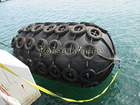
Pneumatic Rubber Fenders
Pneumatic rubber fenders are floating, compressed-air marine energy absorbers. They convert vessel kinetic energy into air compression and elastic cord-layer strain, returning low reaction force to the hull. This guide explains only the engineering: how they work, how they are built, what ISO 17357-1 defines, pressure classes, fender types, deflection physics, and service behavior.
1. What a Pneumatic Rubber Fender Is
A pneumatic rubber fender is a cylindrical body with hemispherical ends, made of reinforced rubber and filled with compressed air at a rated initial pressure.
Core properties:
- Self-buoyant: floats at the waterline
- Deformable: compresses under hull contact
- Recoverable: rebounds after load removal
- Air-spring medium: energy absorbed mainly by gas compression, not solid rubber stiffness
It is not a foam fender, not a solid rubber fender, and not a marine airbag. Airbags launch ships; pneumatic fenders absorb berthing energy.
2. Working Principle: The Air-Spring Mechanism
Step-by-step energy path
1.Vessel approaches
Berthing energy:
E = ½ · M_e · V²
where M_e is effective mass and V is approach velocity.
2.Hull contacts fender
The floating fender sits between hull–hull or hull–structure.
3.Body compresses
- Rubber skin deforms
- Air column shortens
- Internal pressure rises above initial 50/80 kPa
- Synthetic cord layer carries tensile stress
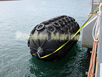
Pneumatic Fenders
4.Energy conversion
- Primary: air compression
- Secondary: elastic strain in rubber + tire-cord skeleton
5.Low reaction force
Because air has no fixed shape and low initial stiffness, the force–deflection curve rises gently. This gives high GEA with low hull pressure.
6.Rebound
Load removed → air re-expands → fender recovers shape.
ISO 17357 reads performance at 60 ± 5% deflection of the fender diameter.
3. Internal Structure: 4 Engineered Layers
| Layer | Material | Function |
| Outer rubber | Marine-grade abrasion compound | UV, seawater, ozone, impact, chafe resistance |
| Cord layer | Angled syntetic tire-cord (nylon/polyester) | Pressure skeleton; burst resistance; stress distribution |
| Inner rubber | Low-permeability airtight compound | Seals compressed air |
| End assembly | Steel flange, bead ring, valve, relief valve | Inflation, pressure control, over-pressure release |
The cord angle is structural, not decorative. P50 and P80 bodies have different cord design and end-ring safety factors.
Safety relief valve is mandatory at ≥ 2500 mm diameter under ISO 17357-1.
4. ISO 17357-1:2014 — What the Standard Defines
ISO 17357 has two parts:
| Part | Pressure class | Use |
| ISO 17357-1 | High pressure: 50/80 kPa | STS, tidal berths, large vessels |
| ISO 17357-2 | Low pressure: ~7kPa | Light-duty, small craft, temporary berthing |
Key defined parameters:
- Initial pressure: P50 / P80
- Deflection test point: 60 ± 5%
- GEA: Guaranteed Energy Absorption
- R: Reaction force
- Tolerance: ±10% on performance values
- Prototype testing required, revalidated periodically by classification society
“Yokohama fender” is a legacy brand name. Technically, the class is “pneumatic rubber fender, ISO 17357-1”.
5. P50 vs P80 — Pressure Physics Only
| Parameter | P50 | P80 |
| Initial pressure | 50 kPa | 80 kPa |
| Stiffness | Lower | Higher |
| Energy absorption | Baseline | ~35-40% higher |
| Reaction force | Lower | Higher |
| Hull pressure | Softer | Harder |
Same diameter/length, different internal pressure field. A P50 body must not be inflated to P80: the cord angle and end-ring safety factor are not interchangeable.
Reference performance at 60% deflection:
- 2500 × 5500 mm P50: ~943 kJ GEA / ~2019 kN R
- 3300 × 6500 mm P50: ~1814 kJ GEA / ~3015 kN R
- 3300 × 6500 mm P80: ~2532 kJ GEA / ~3961 kN R
6. Fender Types by ISO Construction
Type I — Net Type
Chain, wire, or fibre net with tires/rubber sleeves.
- Net takes abrasion, not the rubber skin
- Used in heavy STS, tankers, abrasive quays
Type I Single
Net type with one end metal-free.
- Reduces end-flange deformation risk under severe compression
Type II — Sling Type
No hard net. Thick outer rubber + integral lifting slings.
- Direct hull contact
- Lower marking risk
- Lower abrasion life on rough surfaces
Hydro-Pneumatic
Part air, part water ballast.
- Submerged contact
- Low-freeboard and submarine berthing
ISO 17357-2 adds clamped-end and moulded-end low-pressure variants.
7. Deflection, Reaction Force & Energy Curve
Energy absorption is the integral of reaction force over deflection:
GEA = ∫ R(x) dx (to 60% deflection)
Behavior traits:
- Soft entry: low initial stiffness
- Stable mid-curve: pressure rises gradually
- Peak at 60% deflection test point
- Non-linear: not a linear spring
- Recoverable: minimal permanent set under rated cycle
Pneumatic fenders tolerate angular contact, shear slip, and tidal movement better than fixed solid fenders.
8. Why Floating Matters Mechanically
Fixed fenders are rigid to structure. Pneumatic fenders are free-floating:
- Follow tide/swell/draft
- Stay in contact zone without brackets
- Distribute load across rolling hull
- Decouple hull motion from reaction spike
This is why they are used in:
- Ship-to-ship transfer
- FPSO/offshore platform landing
- Tidal wharves
- Naval alongside replenishment
9. Pneumatic vs Foam-Filled vs Solid Rubber
| Type | Medium | Buoyant | Reaction style |
| Pneumatic | Compressed air | Yes | Soft, air-spring |
| Foam-filled | Closed-cell foam | Yes | Progressive, no pressure upkeep |
| Solid rubber | Rubber compound | No | Stiff, high hull pressure |
Pneumatic fenders give the lowest reaction force per unit energy absorption in floating applications.
10. Fatigue, Inspection & Physics Limits
What degrades performance
- Pressure loss → lower GEA
- Cord fatigue → bulge/laminate separation
- Net corrosion → point loading
- Ozone/cut damage → outer rubber breach
- Over-compression → permanent set
Inspection logic
- Pressure trend over time
- Cuts exposing cord
- Net tension and shackle wear
- Valve function
- Permanent deformation after rebound
Service behavior
- Typical design life: 10–15 years with correct care
- Inflation medium: dry air or nitrogen
- Storage: deflated, shaded, away from ozone/heat
11. FAQ
Are pneumatic fenders the same as Yokohama fenders?
Yokohama is the original brand. Pneumatic rubber fender is the technical class.
Why is 60% deflection the standard test point?
ISO 17357 measures GEA and reaction at 60 ± 5% compression for comparable performance data.
What does the cord layer do?
It holds internal pressure, resists burst, and distributes elastic stress—like a tire skeleton.
Why P50 vs P80?
Different initial pressure changes stiffness, energy absorption, and hull reaction.
Do small fenders need relief valves?
Required at ≥2500 mm diameter; below that only if specified.
12. Summary
A pneumatic rubber fender is an air-spring pressure vessel:
- Reinforced rubber shell
- Compressed-air core
- Cord-layer skeleton
- Floating, recoverable, low-reaction energy absorber
Its performance is defined by ISO 17357 physics—not by appearance, trade name, or net style.
