

Yokohama Pneumatic Fenders: What They Are, How They Work, Types, and Selection Guide
Introduction

Yokohama Pneumatic Fenders
Yokohama pneumatic fenders are air-filled marine fenders originally developed by The Yokohama Rubber Co., Ltd. in 1958. Each fender uses compressed air inside a reinforced rubber body to absorb berthing impact energy.
The original design became the basis of the international standard ISO 17357, and “Yokohama fender” is now used across the marine industry as a general term for this type of pneumatic fender. Today, fenders of this design are produced by many manufacturers and are widely used in ports, ship-to-ship (STS) operations, and offshore installations. They are valued for high energy absorption, low reaction force, and flexible installation.
This guide covers what Yokohama pneumatic fenders are, how they work, the main types, how to select the right size and quantity, and how to install and maintain them.
What Are Yokohama Pneumatic Fenders?
The name describes the origin and the working method:
- Yokohama – refers to Yokohama Rubber, the company that invented and patented this fender design in 1958.
- Pneumatic – the fenders are filled with compressed air, which acts as the cushioning medium.
- Fenders – the plural reflects how they are normally used: several fenders are arranged along a dock or vessel to share the berthing load.
Over the decades, “Yokohama fender” has become a widely used general term for pneumatic fenders of this design.
Structure of the Rubber Body
- Inner rubber liner
- An airtight layer that prevents air leakage.
- Usually made from halogenated butyl rubber because of its excellent air-retention properties.
2. Synthetic cord layers (tyre cords)
- High-strength nylon or polyester cords that bear internal pressure and impact loads.
- Multiple layers are wound at designed angles for balanced strength.
3. Outer rubber cover
- A wear-resistant layer exposed to seawater, UV, abrasion, and impact.
- Usually a blend of natural rubber and styrene-butadiene rubber (SBR).
4. Safety valve
- Releases pressure automatically if the internal pressure rises above the safe limit.
5. Protective covering (optional)
- Chain-and-tyre net, synthetic rope net, or polyurethane (PU) coating.
6. End fittings
- Shackles, chains, flanges, and lifting eyes for suspension and handling.
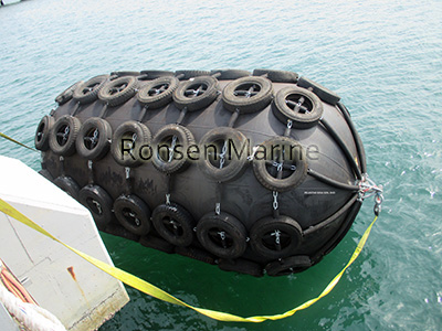
Yokohama Fenders
How Do Yokohama Pneumatic Fenders Work?
The working principle is based on air compressibility and can be broken down into three steps:
- Contact and deformation – The vessel presses against the fenders, and the elastic rubber bodies deform.
- Energy absorption – The air inside is compressed and the pressure rises. The vessel’s kinetic energy is converted into gas compression energy and a small amount of heat. Because air compresses significantly, the fenders deform greatly while keeping reaction force relatively low.
- Rebound – After the vessel moves away, the compressed air and elastic rubber return each fender to its original shape, ready for the next impact.
Performance reference (isothermal approximation):
E ≈ P₀ × V × ln(P₂ / P₀)
Where:
- P₀ = initial air pressure (commonly 50 kPa or 80 kPa)
- V = internal volume of one fender
- P₂ = maximum pressure after compression
This formula shows why larger fenders, higher initial pressure, and a greater number of fenders absorb more energy, and why the rubber body must be strong enough to contain the pressure safely.
Key Advantages
- High energy absorption, low reaction force – protects both hull and berth structure, especially for large vessels.
- Flexible installation – can be mounted on docks, suspended on ship sides, or used in STS operations.
- Adaptable – tolerates uneven berth surfaces, hull inclination, and tidal changes.
- Load can be shared – using several fenders spreads the impact over a wider area.
- Durable in marine environments – when made with the correct rubber compound, they resist seawater, UV, and abrasion.
- Reusable and repairable – minor rubber damage can often be cold-bond repaired.
Common Types of Yokohama Pneumatic Fenders
| Type | Protective covering | Typical application |
| Type I - Chain & tyre net | Heavy-duty chain and tyre protection | Large ports, STS, heavy berthing |
| Type II Rope net | Synthetic rope net | Vessel-mounted, medium duty |
| Net-less (slender type) | PU coating or rubber only | Light duty, clean quays, yacht berths |
| Floating type | Suspended to float on water | STS, floating docks, tidal areas |
Note: “Floating” describes how the fenders are deployed, while Types I, II, and net-less describe the protective covering. These categories overlap.
Common Applications
- Large vessel berthing – oil tankers, LNG carriers, bulk carriers, container ships
- Ship-to-ship (STS) transfer – cargo, bunkering, and offshore supply
- Floating docks and pontoons
- Ports with large tidal ranges
- Offshore platforms and wind-farm support vessels
- Naval, coastguard, and patrol vessels
How to Select the Right Yokohama Pneumatic Fenders
Selecting a set of fenders means deciding both the size of each fender and how many are needed. Selection is usually based on the following five factors:
- Vessel size (DWT) – larger vessels need larger fenders and more of them.
- Berthing velocity – higher speed means more energy to absorb.
- Tidal range – determines suspension length.
- Hull type and dock structure – affects fender spacing and quantity.
- Initial pressure – usually 50 kPa (0.5 bar) for standard use and 80 kPa (0.8 bar) for heavy-duty use.
How Many Fenders Are Needed?
- Fenders are usually placed at intervals along the berth or along the vessel’s side.
- Typical spacing ranges from 10 to 30 metres, depending on vessel size and hull shape.
- For STS operations, fenders are arranged along the longer vessel, with extra fenders near the bow and stern.
- The total energy absorption of all fenders in contact must exceed the vessel’s berthing energy.
Common Size Reference
| Fender size (D x L) | Typical use |
| 500 x 1000 mm | Smalll boats, yachts |
| 1700 x 3000 mm | Medium vessels, tugs |
| 2500 x 5500 mm | Large vessels, STS |
| 3300 x 6500 mm | Very large crude carriers, large STS |
The table above is only a general guide. Actual selection must be based on berthing energy calculations.
Installation Tips
- Inflate each fender to the manufacturer’s recommended pressure before suspending it.
- Use certified chains, shackles, and wire ropes with a suitable safety factor.
- Keep the suspension balanced so each fender hangs vertically and the load is evenly distributed.
- Space the fenders evenly so no single fender takes the full impact.
- For floating installations, leave enough suspension length so the fenders can follow the tide.
- Place fenders opposite the vessel’s main contact points: usually near the bow, stern, and midship.
- For STS operations, follow OCIMF ship-to-ship transfer guidelines.
Maintenance and Inspection
- Before each operation – visual check of all fenders for obvious damage and correct positioning.
- Monthly (high-use) or quarterly (normal):
Check air pressure on every fender with a calibrated gauge and top up if needed.
Inspect the outer rubber for cracks, cuts, bulges, and ozone cracks.
Check the chain or rope net for wear and loose fittings.
Test the safety valves.
- Annually – thorough inspection, including rubber thickness at wear points.
- Storage – keep fenders not in use in a shaded, dry place, away from oil, grease, chemicals, and sharp objects.
Signs you should replace or repair a fender:
- Air pressure drops quickly after inflation.
- Visible bulges or delamination.
- Deep cuts reaching the cord layer.
- A faulty safety valve that cannot be repaired.
With proper care, service life is typically 8–10 years.
Common Mistakes to Avoid
- Too few fenders – the berthing load must be shared, so quantity matters as much as size.
- Over-inflation – exceeds the design pressure and risks bursting.
- Under-inflation – reduces energy absorption and can cause fenders to bottom out.
- Uneven spacing – leaves gaps where the hull can contact the dock directly.
- Specifying only the brand name – always also specify the standard and performance requirements.
- Skipping berthing calculations – guessing the size and quantity often leads to oversized or undersized fenders.
- Buying only on price – low price often means lower rubber quality and weaker cord layers.
Frequently Asked Questions
Q: What are Yokohama pneumatic fenders?
A: They are pneumatic marine fenders originally developed by Yokohama Rubber in 1958. The term is now widely used as a general name for this type of pneumatic fender.
Q: How many Yokohama pneumatic fenders do I need for a berth?
A: It depends on vessel size, berthing energy, and hull shape. Fenders are commonly spaced 10–30 metres apart, with extra fenders near the bow and stern. A supplier should confirm the quantity using ISO 17357 calculations.
Q: Are Yokohama pneumatic fenders the same as pneumatic rubber fenders?
A: Yes. “Yokohama” points to the original inventor, while “pneumatic rubber fender” describes the product itself.
Q: What pressure should they be inflated to?
A: Most manufacturers recommend 50 kPa (about 0.5 bar) for standard applications and up to 80 kPa (about 0.8 bar) for heavy-duty berthing. Always follow the product manual.
Q: What does ISO 17357 cover?
A: ISO 17357 is the international standard that specifies requirements for pneumatic fenders, including performance, materials, testing, and marking.
Q: Can Yokohama pneumatic fenders be reused on different vessels?
A: Yes. One of their main advantages is that they can be moved and reused, provided each fender is correctly sized for the new vessel.
Conclusion
Yokohama pneumatic fenders combine reinforced rubber construction with compressed-air cushioning. Used as a set, they deliver high energy absorption with low reaction force and can be arranged to suit almost any berth or vessel.
When buying, base your choice on vessel size, berthing conditions, tidal range, and ISO 17357 calculations. Correct inflation, even spacing, and regular inspection are the keys to long service life and reliable protection.
