

How Do Pneumatic Rubber Fenders Work in STS & STD Operations?
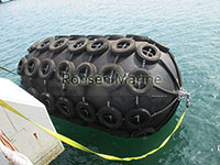
Pneumatic Rubber Fenders
Watch a 300,000 DWT VLCC ease alongside a smaller daughter ship at anchor, and you’ll see four or five black cylinders riding the waterline between them. Those are pneumatic rubber fenders — often called Yokohama fenders — and they are the global default for ship-to-ship (STS) transfer under ISO 17357-1:2014. They work on one physical idea: air is highly compressible, rubber is not. By squeezing trapped air inside a reinforced-rubber cylinder, the fender turns a ship’s kinetic energy into rising internal pressure and elastic cord strain, while returning a remarkably low reaction force to the hull.
The one-paragraph answer
A pneumatic rubber fender absorbs berthing energy by compressing the air inside it. When the hull presses in, the air column shortens, internal pressure rises uniformly, and the synthetic tire-cord skeleton stretches elastically. Because gas has no fixed shape and no high initial stiffness, the force-deflection curve rises gently — that “soft entry” is why pneumatic fenders deliver high energy absorption with low hull pressure, the exact combination STS and STD operations need. Remove the load and the air re-expands; the fender rebounds to shape with no break-in cycle.
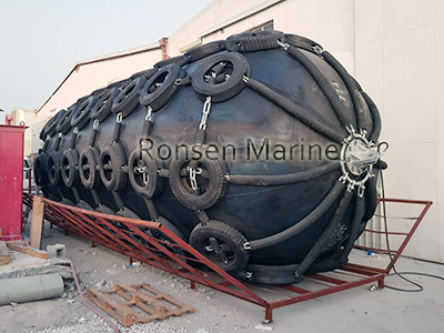
1. The 4-layer build (ISO 17357-1:2014, Type I & Type II)
| Layer | Material | Job |
| Outer rubber | Abrasion, UV, seawater, ozone resistant | Sacrificial shield; take the scrapes |
| Cord layer | Angled nylon/polyeser tire-cord | Burst-proof skeleton; containers pressure |
| Inner rubber | Air-tight membrane | Holds initial pressure (50 or 80 kPa) |
| End flanges + relief valve | Steel, with safety valve | Inflation + autoo over-pressure release (mandatory on > 25mm) |
That cord angle matters more than buyers realise: a P50 body must never be inflated to 80 kPa. The cord-layer angle, end-ring design and safety factors differ between the two ratings, so the classifications are not interchangeable.
2. The physics, step by step
- Vessel approaches → fender floats at the contact point, rising and falling with tide and swell.
- Hull presses → fender compresses axially up to 60% of original diameter (the ISO test point).
- Air column shortens → internal pressure rises uniformly above the 50/80 kPa baseline.
- Kinetic energy converts: E = \frac{1}{2}mv^2 becomes internal air pressure + rubber/cord elastic strain.
- Reaction force stays low and stable → hull pressure stays inside class-society limits.
- Load removed → air re-expands, fender recovers shape, ready for the next hit.
Per ISO 17357 parallel-compression testing, energy absorption is the integral of reaction force over deflection, read at 60% deflection at ≤80 mm/min.
Pneumatic Fenders
3. P50 vs P80: you tune by pressure, not size
This is the most misunderstood spec in the industry.
| Parameter | P50-50 kPa | P80-80 kPa |
| Initial pressure | 50 kPa | 80 kPa |
| Energy absorption | Baseline (GEA) | ~35-40% higher |
| Reaction force | Lower | Higher |
| Hull surface pressure | Lower | Higher |
| Typical use | LNG, aluminium hulls, yachts, nval | VLCC STS, high approach speed, limited fender count |
Example reference values at 60% deflection (one manufacturer’s published data):
| Size | P50 GEA / Reaction | P80 GEA / Reaction |
| 2000 x 3500 mm | 308 kJ / 875 kN | 430 kJ / 1150 kN |
| 2500 x 4000 mm | 663 kJ/ 1381 kN | 925 kJ/ 1815 kN |
| 3300 x 6500 mm | 1814 kJ / 3015 kN | 2532 kJ /3961 kN |
These illustrate the sizing method; they are not a substitute for a calculation against your berth’s design energy. Tolerance per common tender spec: GEA −10%, reaction +10%, skin thickness −10%.
4. How it works differently in STS vs STD
STS (ship-to-ship): both vessels are free-floating, so the berthing energy must account for the mass of both vessels. PIANC WG-211 2024 gives:
M_{sts,c} = \frac{M_1 C_{m1} \cdot M_2 C_{m2}}{M_1 C_{m1} + M_2 C_{m2}}, \quad E_{sts,c} = \left(\frac{1}{2} M_{sts,c} V_{sts,c}^2\right) C_{sts,e}
That combined mass is why the industry default for an Aframax-to-VLCC STS transfer is 3300 × 6500 mm at 50 kPa; where freeboard differential is large or open-water conditions apply, 4500 × 9000 mm may be required. OCIMF guidelines call for a minimum of three fenders, rising to five for vessels above 150,000 tonnes equivalent displacement.
STD/STJ (ship-to-dock): one side is fixed, so the full vessel mass hits the fender system and the structure behind it. Reaction force must be checked against the dolphin and quay capacity, not just the hull.
5. Standards that govern STS pneumatic fenders
Five documents sit behind every credible STS fender spec:
- ISO 17357-1:2014 — product manufacture and testing; defines Type I (net-type, chain-tire net) and Type II (sling-type). Clause 8 requires full-scale prototype performance testing; Clause 9 is the commercial test report.
- OCIMF MEG4 (2018) — Appendix B defines fender performance criteria for STS; Section 6 covers deployment, recovery and inspection. Essential for TMSA / SIRE vetting.
- OCIMF STS Transfer Guide (2013) — the full operational workflow.
- SIGTTO STS Guidelines — LNG-specific, including LNGC-to-FSRU.
- PIANC WG-211 (2024) — replaces WG33; introduces Navigation Conditions (favourable/moderate/unfavourable), the risk-based Partial Energy Factor \gamma_E = \gamma_{E,ref}\gamma_n\gamma_p\gamma_c, and Type Approval angular + horizontal compression testing.
6. The honest trade-off (pneumatic vs foam-filled)
Pneumatic fenders aren’t universally better — they have one fatal weakness: puncture. A skin breach or valve failure deflates them and they lose function. Foam-filled fenders keep working and floating with a cut skin. So the real choice is:
- Pneumatic wins: STS, STD with tide swings, LNG/FSRU, low reaction force, angled contact (air flows, pressure stays uniform), and when you need to ship them deflated.
- Foam-filled wins: permanent berths, unattended/remote sites, debris-heavy ports where a puncture means a deflated fender and a damaged hull, and offshore fixed installations.
7. The failure mode nobody advertises
Deflation isn’t the only risk. The safety relief valve is the one component that prevents catastrophic rupture under accidental over-compression — and on ultralarge fenders it’s mandatory. Pair that with two operating realities: sunlight heats the air inside by +10–15%, so monthly pressure checks are not optional; and cord-layer exposure (cuts >1 cm) is the early warning sign of a body that’s about to fail. Service life is 10–15 years with correct care, not “indestructible forever.”
FAQ
How does a pneumatic fender absorb energy without solid material?
It compresses trapped air; the gas’s compressibility provides the energy-absorption medium, while the cord layer supplies elastic strain. No solid core required.
What’s the difference between STS and STD fenders?
Same product, different energy math. STS must include both vessels’ masses (PIANC WG-211 combined-mass formula); STD checks reaction against the fixed structure.
Is “STQ” a real industry term?
No. The correct terms are STS (ship-to-ship), STD and STJ (ship-to-dock / ship-to-jetty). If you see “STQ” in a supplier’s literature, treat it as a typo and ask for the correct standard reference.
Can I inflate a 50 kPa fender to 80 kPa for more capacity?
Never. Cord angle, end-ring and safety factors differ. You will void the certification and risk burst failure.
