

Cell Rubber Fenders: Sizing, Selection, and Installation Guide
Introduction
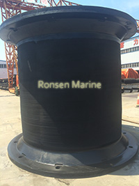
Super cell rubber fenders
Cell rubber fenders are compression-type marine fenders commonly used at ports, terminals, and industrial berths to absorb berthing energy and reduce impact forces between a vessel and a waterfront structure. Their circular, cell-like shape gives them a relatively large surface area and allows them to perform in high-energy berthing applications when properly sized and installed.
A cell rubber fender is not simply a large rubber bumper. Its performance depends on the rubber compound, geometry, compression deflection, mounting system, reaction force, frontal panel, and the berthing conditions at the specific facility. Selecting the correct cell fender requires an engineering review—not just a comparison of product dimensions or catalogue energy values.
This guide explains how cell rubber fenders work, which technical values matter, how to evaluate different sizes, and what to check during installation and maintenance. It is intended for terminal operators, port engineers, consultants, contractors, and marine-equipment buyers.
What Are Cell Rubber Fenders?
Cell rubber fenders are solid marine fenders manufactured from rubber compounds and typically mounted to a quay wall, breasting dolphin, or pile structure. When a vessel makes contact during berthing, the fender compresses and deforms. Part of the vessel’s kinetic energy is absorbed as elastic deformation, while the remainder is dissipated as heat.
Cell fenders are often used at berths where large vessels, high berthing energies, or frequent vessel traffic make smaller fender types unsuitable. They may be installed as individual units or in groups along the berth face, depending on the vessel dimensions, fender spacing, and structural design.
How Cell Rubber Fenders Work
The primary purpose of a cell rubber fender is to absorb energy while controlling the force transmitted to the vessel hull and the berth structure. The relationship between compression, energy absorption, and reaction force is usually presented in the manufacturer’s performance curve.
Three values are essential to the evaluation:
- Berthing energy: the amount of energy the fender system must absorb.
- Reaction force: the force generated as the fender compresses.
- Hull pressure: the pressure transferred to the vessel hull through the fender or frontal system.
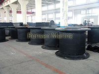
Cell rubber fenders
A fender may have a high energy-absorption rating but still be unsuitable if its reaction force exceeds the allowable load of the quay, dolphin, or vessel. Conversely, a lower-energy fender may be appropriate for a smaller berth even if larger products are available.
Key Performance Factors
Energy Absorption
Energy absorption is the amount of work the fender can absorb at a defined compression level. Published ratings should be reviewed together with the applicable test method, temperature, velocity, contact angle, and deflection.
Berthing energy should be calculated or verified for the project. It can be influenced by vessel mass, approach speed, berthing angle, mooring conditions, eccentricity, and other site-specific factors. A catalogue energy number cannot be transferred directly from one terminal to another.
Reaction Force
Reaction force is the force developed as the fender compresses. It must remain within the structural limits of the:
- vessel hull;
- fender body and anchor system;
- mounting plates and bolts;
- quay wall or dolphin;
- chains, shackles, and frontal frame.
If the reaction force is too high, increasing fender size may not solve the problem. The layout, number of units, frontal system, and structural capacity may also need to be reviewed.
Compression Deflection
Fender performance is normally stated at a defined percentage of compression. The actual operating deflection must be considered because energy absorption and reaction force change with deflection.
The fender should not be compressed beyond its approved design limit. Over-compression may increase reaction force, reduce service life, or damage the mounting system.
Hull Pressure
Hull pressure depends on the contact area between the fender system and the vessel. A frontal panel or face pad may distribute the load over a larger area and help reduce concentrated contact pressure.
The selected frontal arrangement must be compatible with the vessel’s allowable hull pressure and the fender’s performance curve. The panel dimensions, material, bolt pattern, and chain configuration should be confirmed before production.
Contact Angle and Angular Performance
Vessels do not always berth square to the quay. Angular contact can change the effective performance of a fender system. Buyers should obtain correction data for the expected contact angles rather than relying on a generic product description.
Cell fenders may be suitable for a range of berthing conditions, but the acceptable angle must be confirmed using the manufacturer’s tested information.
Common Applications
Cell rubber fenders are often evaluated for:
- container terminals;
- general cargo berths;
- bulk-cargo and mineral-handling terminals;
- oil, gas, and chemical facilities;
- ferry and RoRo terminals;
- cruise-ship and passenger-berth facilities;
- break-bulk terminals;
- breasting dolphins and pile structures;
- multi-user terminals with varied vessel types.
The presence of large vessels does not automatically mean that a cell fender is the correct choice. Selection must also consider berthing energy, reaction force, hull pressure, tidal range, vessel hull form, and the strength of the supporting structure.
Cell Fenders vs Other Marine Fender Types
| Fender type | Typical application | Selection consideration |
| Cell fender | Large fixed berths and high-energy locations | Requires correct sizing, mounting, and frontal system |
| Cone fender | Medium- to large-vessel berths | Often evaluated for angular stability |
| Arch fender | Corners, smaller berths, and space-sentitive locations | Lower capacity than large cell systems |
| Cylindrical fender | General-purpose and pile-protection applications | Frequently used for smaller or specialized installations |
| Pneumatic fender | Ship-to-ship, temporary, or floating operations | Different pressure and handling requirements |
There is no universally superior fender type. The correct choice depends on the vessel, berth design, budget, maintenance plan, and expected operating conditions.
Materials and Construction
Cell rubber fenders are generally produced from marine-grade rubber compounds. Natural rubber, synthetic rubber, or blended compounds may be used depending on the design and operating environment.
Hardness alone does not determine performance. Buyers should also consider:
- tensile strength;
- elongation;
- compression set;
- abrasion resistance;
- ozone and weather resistance;
- ageing characteristics;
- operating temperature range.
Steelwork can include mounting plates, anchor bolts, frontal frames, support chains, shackles, and face pads. For corrosive marine environments, hot-dip galvanizing or stainless-steel components may be specified. The selection should match the exposure level, maintenance access, design life, and project budget.
Frontal Panels and Face Pads
A frontal system may be used to increase the effective contact area, reduce hull pressure, and limit direct abrasion of the rubber surface. UHMW-PE face pads are commonly specified because they can help reduce friction during sliding contact.
Before ordering, confirm whether the frontal panel and face pads are included in the quotation. Also check:
- panel dimensions and thickness;
- bolt pattern and material;
- chain arrangement;
- allowable vertical and horizontal movement;
- panel replacement procedure;
- spare-face-pad availability.
Sizing and Selection Process
A professional cell-rubber-fender specification usually follows these steps:
1. Define the Vessel Parameters
Collect the vessel type, length, beam, draft, displacement or deadweight, hull shape, and expected contact points.
2. Establish the Berthing Conditions
Record normal and maximum approach velocities, berthing angle, tidal range, mooring arrangement, and vessel eccentricity.
3. Calculate the Berthing Energy
Use an appropriate calculation method and apply project-specific factors. The result should be reviewed by a qualified engineer.
4. Select the Initial Fender Size
Compare the calculated energy with the manufacturer’s performance curve. Do not select a size based only on diameter, height, or a single energy value.
5. Check the Reaction Force
Confirm that the reaction force remains within the allowable limits of the vessel and berth structure.
6. Evaluate Hull Pressure
Determine whether a frontal panel or face pad is required to keep hull pressure within the acceptable range.
7. Design the Mounting and Anchor System
Review the quay structure, anchor embedment, bolt grade, plate thickness, and chain tensioning arrangement.
8. Prepare a Technical Quotation
Send complete project data to the supplier and request performance curves, material information, drawings, inspection scope, and delivery terms.
Information Required for a Technical Quotation
To receive a comparable proposal, provide:
- vessel type and dimensions;
- vessel displacement or deadweight;
- normal and maximum berthing velocity;
- expected berthing angle;
- tidal range and operational water levels;
- berth length and fender spacing;
- design berthing energy, if already calculated;
- allowable reaction force and hull pressure;
- quay or dolphin structural details;
- rubber-compound and environmental requirements;
- frontal-panel and face-pad requirements;
- chain, anchor, and mounting specifications;
- quantity, delivery location, and project schedule;
- required certificates, test reports, and inspection criteria.
Standards, Testing, and Documentation
Marine-fender performance should be supported by appropriate technical documentation. PIANC guidance is often used for marine-fender performance principles, while other standards may apply to specific product types or testing methods. Buyers should verify which standard governs the product being purchased.
A strong technical package may include:
- dimensional drawings;
- load-deflection curves;
- energy-absorption and reaction-force data;
- angular-performance information;
- velocity and temperature corrections where applicable;
- rubber-compound test reports;
- dimensional-inspection records;
- factory-acceptance-test documentation;
- third-party witnessing when required by the project.
Documentation requirements vary by manufacturer and project. Important values should not be accepted without adequate evidence, but the absence of one document does not automatically mean that a product is unsuitable.
Installation Checklist
Correct installation is critical to cell-rubber-fender performance. Before and during installation, verify:
- concrete strength and anchor embedment;
- bolt size, grade, and torque requirements;
- alignment of the fender body and mounting surface;
- frontal-panel alignment and clearance;
- chain length and adjustment;
- vertical movement caused by tidal variation;
- corrosion protection of steel components;
- compliance with approved manufacturer and project drawings.
If site conditions differ from the design documents, work should stop until the deviation is reviewed and resolved.
Inspection and Maintenance
A planned inspection program can identify damage before it affects berth safety. Depending on traffic levels and environmental exposure, inspections may cover:
- rubber cracks, cuts, and permanent deformation;
- anchor-bolt movement or corrosion;
- loose or damaged chains and shackles;
- wear of the face pad or frontal panel;
- uneven loading between adjacent fenders;
- debris and marine growth around the fender base;
- impacts outside the design envelope.
High-traffic terminals generally require more frequent inspections. Inspection intervals should be based on vessel frequency, environmental conditions, and findings from previous checks.
Common Specification Mistakes
Choosing by Catalogue Energy Alone
Published energy ratings are valid only for the stated conditions. Size the system using the complete performance curve and project data.
Ignoring Reaction Force
Excessive reaction force can overload the vessel, fender, or berth structure. Energy absorption and reaction force must be evaluated together.
Reusing an Old Layout
Changes in vessel type, berthing speed, tidal conditions, or quay use can make an old specification unsuitable.
Overlooking the Frontal System
The frontal panel and face pad affect hull pressure, friction, and load distribution. They are not merely optional accessories.
Accepting the Lowest Price Without Technical Review
A low purchase price does not guarantee a safe or cost-effective installation. Total installed cost, service life, documentation, and after-sales support should also be considered.
Conclusion
Cell rubber fenders can be an effective solution for high-energy marine berthing when selected through a proper engineering process. The most important step is not choosing the largest available product, but matching the fender system to the vessel, berthing conditions, structural limits, and maintenance plan.
Buyers should request complete performance data, approved drawings, material and inspection documentation, and project-specific calculations before placing an order. A well-specified cell-rubber-fender system can help protect vessels and berth structures while supporting safe and predictable marine operations.
Request a technical quotation: submit your vessel details, berthing parameters, berth layout, design energy, tidal range, and documentation requirements. A qualified supplier should provide a selection proposal and clarify all calculation assumptions before production.
