

Pneumatic Rubber Fenders: Sizing, P50/P80 and ISO 17357-1:2014 Guide
Executive summary
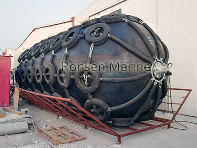
Pneumatic Rubber Fenders
A pneumatic rubber fender is a floating, air-spring energy absorber: compressed air takes roughly 80% of the impact load, the cord-reinforced rubber body the rest. That is why, at the same 60% deflection, it produces far lower hull-surface pressure than a solid-rubber fender of the same energy class. This single property makes it the only compliant choice for STS transfer, large-tide berths, and sensitive hulls (LNG membrane, aluminium, yacht topsides).
Three numbers define a specification: initial pressure 50 kPa (P50) or 80 kPa (P80); performance quoted at 60% deflection as GEA (Guaranteed Energy Absorption) in kJ and reaction force R in kN; and compliance with ISO 17357-1:2014, with a safety relief valve mandatory for bodies of Ø >= 2500 mm. Note that GEA and R must be compared at the SAME deflection – comparing energy at 60% deflection with reaction at 50% is the most common specification error in tender documents.
This guide is written for the buyer and the specifying engineer. It covers how the fender works, P50 versus P80, a worked sizing example, net type versus sling type, the compliance checklist, installation and maintenance, and the mistakes that appear most often in bid specifications.
How a pneumatic rubber fender works

Pneumatic Fenders
The body is built in concentric layers, from outside in: an abrasion-, UV- and seawater-resistant outer rubber cover; bias-wound synthetic tyre-cord plies that hold pressure without ballooning; an airtight inner liner; steel end flanges for the valve and the lifting eyes; and a protective system – chain with aircraft-tyre net (Type I) or a heavy nylon sling (Type II).
On contact the internal pressure rises uniformly, with no local buckling. Kinetic energy converts to air compression plus elastic strain in the cord plies, and the fender recovers its shape when the vessel backs off. Because pressure distributes over the whole contact area, surface pressure on the hull stays low – the reason naval, LNG and yacht operators specify pneumatic rather than solid fenders.
Performance is always quoted at 60% deflection
GEA (Guaranteed Energy Absorption) and reaction force R are the two numbers to compare on a datasheet. Both are measured at 60% deflection unless the manufacturer states otherwise. A higher GEA number at a lower deflection is not comparable – always check the deflection column before comparing suppliers.
P50 vs P80: same size, different job
| Rating | Initial pressure | Energy absorption | ||
| P50 | 50 kPa | Baseline (ISO GEA) | ||
| P80 | 80 kPa | Approx. 35-40% higher |
The two grades are NOT interchangeable. Cord angle, end-ring design and safety factor differ between P50 and P80, so inflating a P50 body to 80 kPa invalidates the type test and voids the warranty. The rating is moulded into the body together with the standard, size, serial number, maker and year of manufacture.
Typical performance figures (values vary by manufacturer; tolerance typically +/-10%):
| Size (mm) | Grade | GEA @ 60% (kJ) | |
| 2500 x 5500 | P50 | 943 | |
| 3300 x 6500 | P50 | 1814 | |
| 3300 x 6500 | P80 | 2532 |
Sizing the fender: the calculation
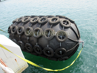
Floating Pneumatic Rubber Fenders
Design berthing energy is calculated by the PIANC method: E = 0.5 x M x V^2 x Cm x Ce, where M is displacement in tonnes, V is approach velocity in m/s, Cm is the added-mass coefficient and Ce is the eccentricity coefficient. Apply a safety factor of 1.5 to 2.0, then pick the smallest standard size whose published GEA exceeds the result.
Worked example
A 120,000-tonne vessel approaches at 0.15 m/s, with Cm = 1.5 and Ce = 0.5. Using a safety factor of 1.5, the required GEA is 0.5 x 120000 x 0.15^2 x 1.5 x 0.5 x 1.5 = 2025 kJ. A 3300 x 6500 mm P80 (GEA 2532 kJ) is the smallest standard size that clears it. With P50 the same size only reaches 1814 kJ and would be underspecified – this is exactly where specifying P80 buys capacity without increasing the footprint.
Two checks remain after the energy calculation. First, the reaction force R must not exceed what the quay foundation can take. Second, the hull-surface pressure must stay within the allowable for the vessel’s shell plating or coating. Sizing by DWT alone is not a valid method.
Coefficients at a glance
| Coefficient | Typical range | What raises it |
| Cm – added mass | 1.2 to 1.8 | Shallow water, restricted channel, vessel geometry |
| Ce – eccentricity | 0.3 to 0.7 | Off-centre berthing, long vessel, single-point contact |
| Safety factor | 1.5 to 2.0 | Uncertain approach control, tidal range, exposed site |
Net type vs sling type
| Type | Best for | Watch out for |
| Type I – chain and tyre net | VLCC / LNG STS, permanent berths, rough seas | Tyres can scuff delicate hull paint |
| Type II – nylon sling | Yachts, naval, cruise, calm-water temporary berthing | Less abrasion protection; avoid sharp edges |
The choice is often made on hull sensitivity rather than energy class. A net-type fender on an LNG carrier or a yacht topside is a documented coating-damage risk; a sling-type fender on a permanent berth in exposed water leaves the cover unprotected. Specify the type explicitly – “Yokohama type” alone is not a specification.
ISO 17357-1:2014 compliance checklist
A compliant line item in a tender or purchase order reads:
Pneumatic rubber fender, ISO 17357-1:2014, P50, 3300 x 6500 mm, Type I chain-tyre-net, with safety relief valve, mill certificate and third-party class approval (ABS / BV / DNV / CCS / LR).
The following items belong in the inspection and acceptance record:
- GEA and reaction force at 60% deflection, with prototype and production test reports
- Cord reinforcement specification and inner / outer rubber material test
- Relief valve present for bodies of Ø >= 2500 mm
- Body marking: standard, size, pressure rating, serial number, maker, year
- Dimensional tolerance: diameter +10% / -5%, length +10% / -5%
Mill certificates and class approvals (BV, DNV, ABS, CCS, LR) should be referenced on the product page and in the tender response, not buried in a quality manual.
Installation: the points that decide service life
Horizontal spacing should be 1.5 to 2.0 times the fender length, so that contact is shared rather than concentrated on a single unit.
Freeboard differential in STS operations must be calculated before the fender train is rigged – a mismatch here is a frequent cause of fender climb and line failure.
Lifting eyes, shackles and chain are rated components. Replace any link showing stretch, crack or corrosion pitting; do not weld a repair.
The safety relief valve must be accessible for inspection and set to the pressure stated on the body marking. A valve that is painted over is a valve that cannot work.
Maintenance schedule
| Usage intensity | Check interval | What to record |
| Heavy | Weekly | Pressure, cuts, valve, chain wear, net condition |
| Moderate | Monthly | Pressure, cover condition, mooring line chafe |
| Occasional | Before each use | Pressure, visible damage, valve operation |
Inflate with dry air or nitrogen and keep pressure within +/-10% of rated. Wash with fresh water after seawater exposure. Inspect for cuts, valve leaks and chain corrosion. Store deflated, shaded and away from ozone sources. Expect 6 to 10 years of service with correct care; the single most common cause of early failure is chronic under-inflation, which forces the cords to carry load they were not designed for.
Six specification mistakes we see repeatedly
- Sizing by DWT instead of displacement and approach velocity.
- Ignoring reaction force against the quay foundation and allowable hull pressure.
- Putting chain-net fenders against LNG or yacht hulls.
- Oversizing diameter – too large a gap makes gangway and cargo transfer harder.
- Forgetting freeboard differential in STS and correct horizontal spacing.
- Buying on unit price instead of GEA plus certification plus service life.
Application map
| Application | Typical choice | Reason |
| LNG / chemical STS | P50, Type II sling, often custom length | Low surface pressure, coating protection |
| VLCC / tanker berth | P80, Type I net | High energy, permanent exposure |
| Naval / patrol craft | P50, Type II | Hull sensitivity, low reaction |
| Yacht marina / superyacht | P50, Type II, soft sling | Gelcoat and topside protection |
| Offshore wind / CTV | P50 or P80, Type I | Tidal range and exposed site |
Frequently asked questions
What pressure should a pneumatic rubber fender be?
50 kPa for P50 (lower hull pressure) or 80 kPa for P80 (maximum absorption). Never exceed the rated pressure of the body, and keep it within +/-10% in service.
Can one fender size fit every berth?
No. Tidal range, hull shape, berthing energy and approach angle vary by site. Floating pneumatics suit tidal ranges above 3 to 4 m; for the rest, consult a marine engineer.
What is the difference between GEA and rated energy?
GEA is the guaranteed minimum energy absorption at 60% deflection, backed by type test. It is the only number that can be compared fairly between manufacturers.
How long do they last?
6 to 10 years with correct inflation and storage. Chronic under-inflation and untreated cord exposure after a cover cut are the two main causes of early failure.
Author: [Kellee], Marine Engineer, [Ronsen Marine]
15 years specifying fendering systems for LNG, offshore wind and naval berths. All performance figures in this guide are indicative; confirm values against the manufacturer’s current type-test report before specifying.
