

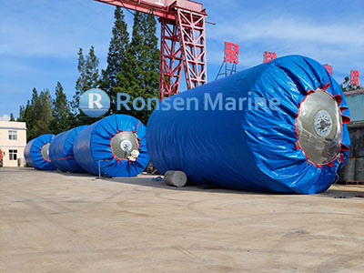
Foam Filled Fenders
Foam Filled Fenders: Complete Guide to EVA Closed-Cell Marine Fenders
Foam filled fenders (EVA foam fenders / closed-cell foam fenders) for ship-to-ship transfer, ship-to-dock berthing and offshore mooring. Unsinkable, zero air-pressure upkeep, reinforced polyurea skin, energy absorption 6.5-9,126 kJ. Net type, chain type and sling type. Request a quote and sizing proposal.
What Are Foam Filled Fenders?
A foam filled fender is a cylindrical or oval marine fender whose core is a block of closed-cell ethylene-vinyl acetate (EVA) foam, permanently encased in a reinforced polyurea or polyurethane elastomer skin. Also known as EVA foam fender, closed-cell foam fender, foam-filled fender or foam dock fender, it works by
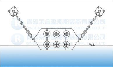
compressing the foam under berthing load and re-expanding as the vessel backs off. There is no air chamber, no inflation valve and no pressure to maintain.
This is the critical distinction from pneumatic fenders: where a pneumatic fender stores energy as compressed air, a foam fender stores it as compressed foam. The skin is bonded to the core so it cannot peel off, and
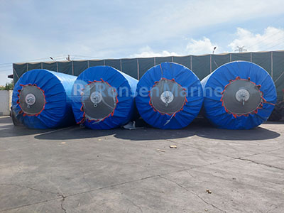
Foam Fenders
because the core is closed-cell, a torn skin still leaves a fender that floats and works – it does not deflate and collapse. ISO 17357-1:2014 classifies foam filled fenders as Type II; pneumatic fenders are Type I.
Foam Filled Fenders: Key Specifications
All values below are reference figures for specification work. Energy absorption and reaction force are measured at 60 +/- 5% deflection under the ISO parallel-compression test. Confirm the final figures against the manufacturer’s performance curves and certification package before ordering.
| Parameter | Standard range / value | Notes |
| Core material | Closed-cell EVA foam | Cross-linked; does not absorb water |
| Core density | 60, 80, 100, 120 kg/m3 | Higher density = stiffer, more energy |
| Skin | Reinforced polyurea / PU elastomer, 15-25 mm | Abrasion, UV and seawater resistant |
| Diameter (D) | 0.5 – 4.5 m | Common stock: 1.0 / 1.5 / 2.0 / 2.5 / 3.3 / 4.5 m |
| Length (L) | 1.0 – 10.6 m | Matched to D; special lengths on request |
| Energy absorption | 6.5 – 9,126 kJ | At 60% deflection; +/- 10% |
| Reaction force | 51 – 9,064 kN | Must stay within hull and berth limits |
| Compression | Approx. 60% at rated load | Non-linear softening curve |
| Type | Net type, chain type, sling type | See Types section below |
| Standard | ISO 17357-1:2014 Type II, PIANC 2002 | Prototype and production tested |
| Service life | 10 – 15 years | With skin and connection checks every 6 months |
| Colour / marking | Any RAL; colour-impregnated, UV-stable | House colours, logos, reflective tape |
Performance Table: Energy Absorption and Reaction Force
Values are minimum guaranteed figures at 60 +/- 5% deflection; the actual curve must be taken from the supplied performance chart. Core density and skin reinforcement等级 change the result, so the same nominal size can appear with different figures across catalogues – always match the table to the declared density.
| Size D x L (mm) | Energy (kJ) | Reaction (kN) | Size D x L (mm) | Energy (kJ) | Reaction (kN) |
| 500 x 1000 | 6.5 | 51 | 2000 x 3500 | 386 | 875 |
| 700 x 1500 | 24 | 137 | 2500 x 4000 | 798 | 1381 |
| 1000 x 1500 | 38 | 182 | 2500 x 5500 | 1158 | 2019 |
| 1000 x 2000 | 52 | 257 | 3300 x 4500 | 1446 | 1884 |
| 1200 x 2000 | 74 | 297 | 3300 x 6500 | 2231 | 3015 |
| 1350 x 2500 | 121 | 427 | 3300 x 10600 | 3768 | 5257 |
| 1500 x 3000 | 180 | 579 | 4500 x 9000 | 5845 | 5747 |
| 1700 x 3000 | 226 | 639 | 4500 x 12000 | 9126 | 9064 |
Foam Filled vs Pneumatic (Yokohama) Fenders
The choice is rarely about which is “better” – it is about which failure mode your operation can tolerate. A pneumatic fender gives lower hull pressure for the same energy, but only while it is correctly pressurised. A foam fender gives up some performance per unit size and costs more upfront, but removes the pressure-maintenance failure mode entirely.
| Parameter | Foam filled (Type II) | Pneumatic (Type I) |
| Energy mechanism | Closed-cell foam compression | Compressed air spring |
| Air pressure required | No | Yes – 50 or 80 kPa initial |
| Pressure checks | None | Monthly, +/- 10% of rated |
| Unsinkable | Yes, even if skin is torn | No – a puncture collapses it |
| Hull pressure | Low | Lowest |
| Energy per unit size | Higher | Lower |
| Upfront cost | Higher | Lower |
| Weight | Heavier, does not deflate for storage | Light, deflatable and foldable |
| Typical use | No-maintenance sites, offshore, tidal STS, sensitive hulls | STS, tidal STD, temporary berthing |
Types: Net, Chain and Sling
| Type | Construction | Pros / cons | Typical use |
| Net type | Polyester web or chain net with rubber sleeves over the skin | Best abrasion and puncture protection; heavier | Offshore, steel-on-steel, permanent berths |
| Chain type | Heavy-duty chain net with shackles and swivels | Maximum ruggedness; hardest to handle | Tankers, barges, rough seas, heavy fendering |
| Sling type | Integral lifting slings, no hard net | Lightweight, fast deploy, non-marking options | Yachts, naval, cruise, calm-water berthing |
Connections scale with size: pad eye for the smaller range, lifting lug and shackle for mid sizes, towing ring or swivel joint for the largest. A reinforced wear sleeve is recommended wherever the fender contacts a steel hull, mooring chain or quay edge. Custom shapes – D-shaped for quay walls, square or rectangular for corners and pilings, donut for single-point mooring – are available because the foam core can be cut and bonded to almost any geometry.
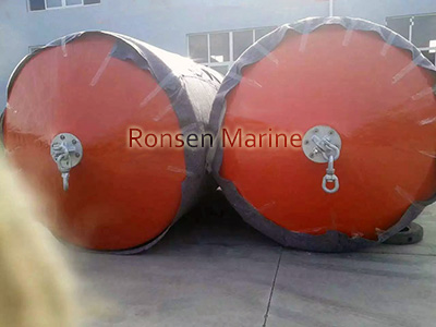
Guard Foam Filled Fenders
Skin and Core: What Actually Takes the Load
The skin is a sprayed or moulded polyurea / polyurethane elastomer reinforced with nylon or aramid fibre, typically 15-25 mm thick. It resists abrasion, UV, ozone, seawater and marine-growth fouling. Because it is chemically bonded to the foam core, it cannot separate under cyclic compression – a common failure point in poorly made foam fenders.
The core is cross-linked closed-cell EVA foam. Cross-linking matters: non-cross-linked foam creeps under sustained load and takes a permanent set, so the fender sits lower in the water after a heavy berthing. Density is the main tuning knob – 60 kg/m3 gives a soft, low-reaction fender for sensitive hulls, while 120 kg/m3 is aimed at high-energy berthing where reaction force is less of a concern. A higher-density core also gives better performance in cold water, where pneumatic fenders lose pressure as the air cools.
How to Size a Foam Filled Fender
Sizing follows the same PIANC berthing-energy equation as pneumatic fenders – the energy physics are identical, only the energy-absorption mechanism differs:
- Step 1 – Berthing energy: E = 0.5 x Cm x Mv x Vb^2 x Ce x Cs x Cc, where Mv is displacement in tonnes and Vb is velocity normal to the berth in m/s.
- Step 2 – Because Vb is squared, doubling the berthing velocity quadruples the energy demand. Approach speed is the dominant variable, not vessel length.
- Step 3 – Select a fender whose rated energy absorption meets or exceeds E, then verify reaction force against the hull’s allowable pressure and the dock structure.
- Step 4 – Apply the angle correction factor (1.00 at 0 deg, 0.90-0.95 at 3 deg, 0.75-0.85 at 6 deg, which is the usual upper limit for standard ports) and check vertical positioning across the tidal range.
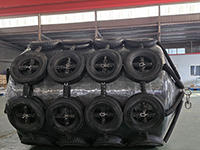
Net Chain Foam Filled Fenders
Worked example – a cited PIANC case with approach velocity 0.15 m/s and displacement 59,800 tonnes yields approximately 605 kNm of berthing energy, comfortably covered by a 2500×4000 mm foam fender (798 kJ). Tell us displacement, normal approach velocity, berthing angle, water depth, tidal range and dock type, and we will return a written proposal with size, core density, type, quantity, arrangement drawing and certification documents.
Installation and Layout Rules
- Mount the fender bottom at least 300 mm above the lowest water level.
- Space fenders at 1.5-2.0 times the fender length.
- At a berth with a 12-metre tidal range, one line of floating fenders can replace three tiers of fixed rubber fenders.
- Use guy chains or guy ropes with swivel joints; attach only to the rated pad eyes, lugs or towing rings.
- Keep the fender clear of sharp quay edges – the skin is tough but a steel corner will eventually cut it.
Maintenance and Service Life
- No pressure checks – this is the principal maintenance saving over pneumatic fenders.
- Inspect skin for cuts, abrasion and delamination every 6 months; repair small cuts before water reaches the core.
- Check net, chains, shackles, swivels and pad eyes for wear and corrosion on the same schedule.
- Wash salt and marine growth off after use; store shaded, away from ozone and heat sources.
- Typical service life is 10-15 years, longer than pneumatic fenders in the same duty.
Foam Filled vs Pneumatic vs Solid Rubber Fenders
| Feature | Foam filled | Pneumatic | Solid rubber (cell/cone) |
| Energy mechanism | Foam compression | Air spring | Solid-rubber compression |
| Floats with tide | Yes | Yes | No – fixed to quay |
| Pressure upkeep | None | Required monthly | None |
| Unsinkable | Yes | No | N/A |
| Hull pressure | Low | Lowest | Higher |
| Weight | Heavier | Light, deflatable | Heavy |
| Upfront cost | Highest | Lowest | Mid |
| Best for | No-maintenance, offshore, tidal STS | STS, tidal STD, temporary | Permanent high-traffic dock |
Applications of Foam Filled Fenders
- Ship-to-ship oil, LNG and product transfer, including lightering and bunkering.
- Ship-to-dock berthing at tidal wharves and marginal berths.
- Offshore wind CTV and SOV docking, where maintenance access is limited.
- FPSO and FSU offloading, SPM and CBM buoy mooring, floating docks and marinas.
- Cruise terminals, naval berthing and submarine tendering (non-marking sling type).
- Quay walls, corners and pilings using D-shaped or rectangular custom profiles.
- Salvage, emergency lay-by fendering and any site where pressure upkeep is unavailable.
Pre-Installation Checklist
- Confirm ISO 17357-1:2014 Type II compliance and the declared core density – performance scales directly with it.
- Verify rated energy absorption and reaction force at 60% deflection against the manufacturer’s curves.
- Check that reaction force stays within the hull’s allowable pressure and the berth’s structural capacity.
- Confirm the angle correction factor for the expected berthing angle (6 deg is the usual port upper limit).
- Size the tidal range and set fender bottom at least 300 mm above lowest water level.
- Verify connections (pad eye / lug / towing ring / swivel) are rated for the hanging load plus berthing force.
- Fit a wear sleeve wherever the fender contacts steel, chain or quay edge.
Certificates and Documents to Request
- Prototype type-approval test to ISO 17357-1:2014 Type II.
- Core-material density and cross-linking test report.
- Skin material specification: thickness, reinforcement, abrasion and UV resistance.
- Third-party class report – ABS, BV, DNV, CCS, LR, GL, NK, KR, RINA or RS as required by the flag state.
- Performance curves showing energy absorption, reaction force and hull pressure at 60% deflection.
- Bond test between skin and core – separation under cyclic load is the main failure mode.
- Traceability code on each fender body matched to the test report.
Frequently Asked Questions
Q: What is a foam filled fender? A: A marine fender with a closed-cell EVA foam core inside a reinforced polyurea or PU skin. It absorbs berthing energy by compressing the foam and needs no air pressure.
Q: Are foam filled fenders the same as Yokohama fenders? A: No. Yokohama (pneumatic) fenders are ISO 17357 Type I and use compressed air. Foam filled fenders are Type II and use compressed foam.
Q: Do foam filled fenders need pressure checks? A: No – there is no air chamber. That is their main advantage over pneumatic fenders in remote or offshore locations.
Q: What happens if the skin is punctured? A: The fender keeps floating and working because the core is closed-cell foam. Repair the skin at the next opportunity, but the fender does not collapse.
Q: How long do foam filled fenders last? A: Typically 10-15 years with six-monthly skin and connection inspections – generally longer than pneumatic fenders in the same duty.
Q: Which core density should I choose? A: 60-80 kg/m3 for sensitive hulls where low reaction force matters; 100-120 kg/m3 for high-energy berthing where reaction force is acceptable.
Q: Why does cold water favour foam fenders? A: A pneumatic fender loses internal pressure as the air cools, reducing performance. Foam compression is not temperature-sensitive.
Q: Can foam fenders be made in custom shapes? A: Yes – D-shaped for quay walls, square or rectangular for corners and pilings, donut for SPM. The foam core can be cut and bonded to the required geometry.
Q: How many fenders do I need? A: It depends on berthing energy, not vessel length. Send us displacement, approach velocity, berthing angle, tidal range and dock type for a layout drawing and quantity.
Request a Quote and Sizing Proposal
Send us vessel displacement, normal berthing velocity, berthing angle, water depth, tidal range and dock type, and we will return a written proposal with fender size, core density, type, quantity, arrangement drawing, certification package, unit price, lead time and incoterms. Minimum order quantity is one piece; OEM, custom shapes and non-standard sizes are accepted.