

What Is a Mooring Bollard? The Complete Guide to Types, SWL Sizing, Standards & Installation
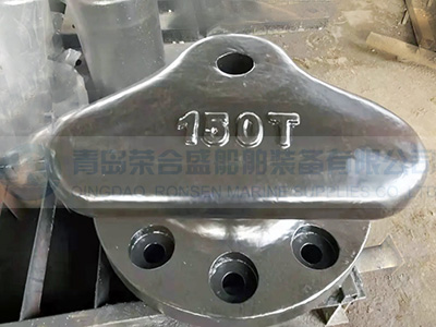
Mooring Bollards
Quick Answer: What Is a Mooring Bollard?
A mooring bollard is a robust, vertically mounted deck fitting — usually a cast or forged steel post with one or more horns — that serves as the fixed anchor point where mooring lines (ropes, wires, or chains) are secured to hold a vessel alongside a quay, jetty, dock, pier, or ship deck.
Its job is to absorb and transfer the full lateral, longitudinal, vertical, and uplift forces generated by environmental loads — wind, current, waves, tides, passing ships, and the vessel’s own motion — into the quay or deck structure beneath it. A bollard is not a standalone item: the bollard body, anchor bolts, grout layer, base plate, and concrete foundation form one continuous load path, and every link must match the design load.
Get the sizing, installation, or maintenance wrong and the consequences are severe: parted lines with lethal snap-back, uncontrolled vessel drift, collisions with infrastructure or neighbouring ships, crew injury or fatality, and major liability. That is why bollards are classed as safety-critical marine equipment, governed by strict international standards and classification society rules.
How a Mooring Bollard Works
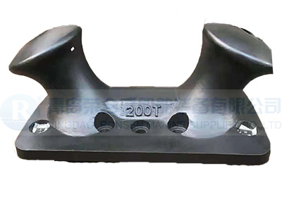
Marine Bollards
When a mooring line is made fast to a bollard, the line tension has two components:
- Horizontal component (T × cos θ) — resists wind, current, and wave forces to keep the ship on station.
- Vertical component (T × sin θ) — creates uplift on the bollard head, anchor bolts, base plate, and foundation. This uplift is what most often controls the design.
A well-designed bollard spreads that combined load across the deck or quay through its base flange and anchor system, so no single point carries a stress concentration that could crack the concrete or pull out a bolt.
The horns or head shape keep the line from slipping off under changing lead angles as the tide rises and falls or the ship changes draft during cargo operations. The key design principle: the fixing system should fail before the maritime structure does, limiting damage to the asset. This is often achieved with waisted (break-off) holding-down bolts that part in a controlled way under excessive load.
Types of Mooring Bollard
T-Head (Tee) Bollard
The most common general-purpose design worldwide, with a horizontal crossbar on top forming a T shape. Simple, rugged, low-maintenance, and narrow in footprint — ideal where deck or quay space is limited. Suitable for line loads up to around 300 tonnes, and accommodates steeper rope angles. Often the default choice for cargo terminals.
Staghorn (Twin Horn / Horn) Bollard
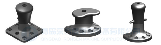
Steel Marine Mooring Bollards
A direct upgrade of the double bitt, with two horns curving away from the neck. Holds two mooring lines at once and handles large tidal-range variations and steep line angles particularly well. Common capacity range up to about 250 tonnes. Favoured in busy multi-vessel berthing areas.
Kidney (Curved / Oval) Bollard
An oval or kidney-shaped head with a smooth curved top and no sharp edges. The larger surface area spreads line pressure more evenly and makes it harder for a rope to jump off accidentally, reducing chafe. Best suited to low-to-medium tidal ranges; an economical solution for confined dock areas.
Double Bitt Bollard
Two vertical posts, one in front of the other, joined at the base. The twin-post layout makes it easy to separate and handle multiple lines, and gives extra stability under load. Common on both ship decks and dock structures, especially where lines must be kept clearly organised.
Single Bitt Bollard
The simplest form — a single vertical post, often with one or two horns or studs. Light load capacity, widely used on ship decks, small jetties, and yacht marinas.
Pillar (Single Column) Bollard
A larger, heavier cylindrical or square post for heavy-duty mooring in areas subject to high loads. Can accept mooring lines from all horizontal directions, unlike most other types. Often specified for large commercial ports, naval facilities, and offshore terminals.
Specialist Variants
Tricorn (three-horn) bollards for multi-directional lines; camberhead/camber-top bollards that slope to reduce line angle and chafe; cleat bollards; Japanese pillar and T-head designs; conical bollards with lifting lugs; roller bollards that reduce line wear; and shock-absorbing (energy-dissipating) bollards that protect both vessel and dock. Storm bollards — typically rated above 250 tonnes — are added to mooring patterns for extreme weather.
Materials & Grades
Material choice is a balance between strength, corrosion resistance, castability, weldability, and cost. The four common options:
| Material | Typical Grade | Best For |
| Ductile (spheroidal graphite) iron | EN-GJS-450-10 / 500-7 / 600-3; ASTM A536 65-45-12 / 70-50-5; QT450-10 / QT500-7 | Shore bollards, commercial ports — mainstream choice, good shock resistance, corrosion-resistant, cost-effective |
| Cast steel | ASTM A27 Class B; ASTM A148 80-50; A216 WCB; G20Mn5 | Super-large container terminals, heavy-tonnage vessels, high load capacity |
| Forged / structural steel | ASTM A572 Grade 50; A36; Q235 / Q355 | Custom heavy-duty and high-strength fabricated bollards |
| Stainless steel | 316 / 316L | Yacht marinas, offshore platforms, luxury port projects — highest seawater corrosion resistance |
| Aluminium alloy | 6061-T6 | Where weight matters: offshore platforms, yachts, lightweight structures |
Ductile iron is less susceptible to corrosion than cast steel, which rusts quickly and needs frequent repainting to retain full strength. Cast steel and forged steel offer higher load capacity but require extra anti-corrosion coating. Stainless steel costs more but is the premium long-life option for yacht marinas and offshore platforms. For low-temperature service, manganese or nickel alloying is added for toughness.
SWL, MBL & How to Size a Bollard
SWL (Safe Working Load) is the rated tensile capacity of the bollard — the single most important selection parameter. Do not confuse it with MBL, which refers to the mooring rope, not the bollard.
Design uses three limit states:
- SLS (Serviceability Limit State) — normal daily operations and standard weather; the structure must not suffer permanent deformation.
- ULS (Ultimate Limit State) — extreme conditions, storm, brake-mode winches; typically a 1.5× factor per Eurocode and BS 6349 to ensure survival.
- ALS (Accidental Limit State) — human error, winch failure, or uneven line tension, such as two lines reaching full MBL simultaneously; the highest safety threshold.
The characteristic SLS load for a bollard is commonly estimated as:
FSLS = N × 0.6 × MBL
Where N = number of mooring lines on the bollard, and 0.6 is the standard tension factor (winch rendering capacity, per OCIMF MEG).
Always validate the final rating with a full mooring analysis and the relevant standard. The table below is a preliminary guide only:
| Vessel Displacement | Approx. Bollard Rating |
| Up to 2,000 tonnes | 10 tonnes |
| 2,000 – 10,000 tonnes | 30 tonnes |
| 10,000 – 20,000 tonnes | 60 tonnes |
| 20,000 – 50,000 tonnes | 80 tonnes |
| 50,000 – 100,000 tonnes | 100 tonnes |
| 100,000 – 200,000 tonnes | 150 tonnes |
| Over 200,000 tonnes | 200 – 300+ tonnes (storm bollards ≥250 t) |
Site modifiers matter. If the berth expects high winds, strong currents, or other adverse loads, increase capacity by at least 25% (some guidance calls for 25% or greater). Add roughly 1.25× for currents over 3 knots or winds above 40 knots, and increase SWL by 10–15% for steep vertical line angles. Fatigue must also be checked for cyclic loading over the design life.
The common mistake is sizing from static vessel displacement alone and ignoring dynamic loads from wind, waves, passing vessels, and changes in draft during cargo operations. The other is forgetting that the bollard’s capacity is only as good as the quay foundation designed to accept the same peak forces.
Standards, Certification & Testing
Mooring bollards must comply with a framework of international standards. Key references include:
- BS 6349-4 — Maritime works: code of practice for the design of fendering and mooring systems (current edition BS 6349-4:2026).
- PIANC guidelines and ROM 0.2-90 / 3.1-99 — mooring loads, layout, line angles, and spacing.
- OCIMF MEG4 — Mooring Equipment Guidelines for terminal and vessel safety, load distribution, and structural redundancy.
- ISO 3911:2016 — general marine mooring bollard requirements.
- UFC 4-159-03 and EAU 2012 — design of moorings and waterfront structures.
- IACS Unified Requirement S11 Rev.8 — structural integration and fatigue resistance.
- DNV-ST-N001, DNVGL-ST-C105; ABS, LR, BV, CCS, ClassNK, GL, EC rules for classification.
Local regulations always take precedence — check the applicable national code first.
Quality assurance should include 100% material traceability, full mechanical-property verification, weld quality checks, and NDT (ultrasonic testing and magnetic particle inspection) on critical welds. New bollards are routinely proof-load tested at 1.1 to 1.5 times design load with third-party witnessing available, and supplied with a Certificate of Conformity (CoC) and test report. A load rating (SWL) plate must be affixed to every bollard.
Layout: Spacing, Line Angles & Mooring Patterns
BS 6349-4 and ROM 02-90 recommend bollards at intervals of 15 to 30 metres along a continuous quay — 30 m for vessels above 20,000 tonnes displacement, and 15–30 m for smaller vessels. Another common rule is 15% of the length of the shortest ship using the berth. For island berths, mooring points should sit 35–50 m from the berthing line of the largest vessel.
Spacing often coincides with fender placement — either at the same points as fenders or midway between them, and often halfway between expansion joints on continuous structures. Mooring lines should be long (ROM 02-90 advises against lines shorter than 30 metres) and limited in number.
Recommended line angles (BS 6349, ROM 0.2-90):
| Line Type | Recommended Angle |
| Head & stern lines | 45° ± 15° |
| Breast lines | 90° ± 30° (as perpendicular as possible to the vessel axis) |
| Spring lines | 5 – 10° (as parallel as possible to the vessel axis) |
| Vertical line angle | As small as practicable, preferably ≤ 25°; Trelleborg designs allow up to 75° |
| Horizontal acceptance | Typically up to ±90° (pillar bollards accept all horizontal angles) |
Bollards are generally designed for a maximum of two attached lines unless a longer neck is specially designed for three. Mooring arrangements must also clear the freeboard, fenders, and other quay furniture so lines cannot snag or damage them.
Where Mooring Bollards Are Used
- Container terminals, passenger and ro-ro terminals, general cargo and bulk carrier berths.
- Tanker terminals and Single Point Moorings (SPM), FPSO and offshore loading systems.
- Marinas and yacht clubs — stainless or low-capacity ductile iron bollards.
- Ship decks and shipyards — deck-mounted bollards for vessel-to-vessel connections, towing, and construction/repair positioning.
- Naval and coastguard bases, fishing ports, inland river and canal terminals.
- Offshore wind turbine platforms — mooring points for crew transfer and maintenance vessels.
- Aquaculture cages, floating docks, research stations, and waterfront infrastructure projects.
Components of a Mooring Bollard Assembly
- Body (head and neck) — the vertical post or structure that takes the line tension; high-strength cast or forged steel.
- Horns / head shape — T, staghorn, kidney, tricorn, or curved; provide multiple line attachment points and retain the line.
- Base plate / flange — bolts or welds the body to the foundation and spreads the load into the supporting structure.
- Anchor bolts — galvanised or stainless steel (typically ISO 898 Gr. 4.8 / 8.8, ASTM A325, or F1554 Gr. 105), checked for number, material grade, shear strength, and pull-out resistance.
- Grout layer — non-shrink cementitious grout, minimum 60 MPa, eliminates voids under the base flange so compressive stress is uniform.
- Lifting lugs — for crane handling during installation.
- Finish — hot-dip galvanising, epoxy primer, zinc-rich primer plus high-build epoxy, or polyurethane topcoat.
- Load rating (SWL) plate — states the safe working load for safe mooring operations.
- Bollard cap — protects the top of the unit and improves appearance.
Installation: Getting the Load Path Right
Correct installation is not optional — it is the difference between a 20-year service life and sudden failure. The sequence:
- Position and fix the anchor template accurately on the rebar cage before the concrete pour. Anchors placed in sleeves and penetrating the full depth of the member can be replaced more easily later.
- Pour and fully cure the concrete foundation to design strength.
- Prepare the surface — roughen the concrete deck, remove all debris with pressurised air, and verify bolts are straight and level.
- Grout the base. Use non-shrink grout (≥60 MPa), shim and align the base flange, leave a gap with removable shims, isolate the area with boundary forms, fill grout at least 5 mm above the bottom of the flange, and form a 45° chamfer at the periphery before curing. Cover immediately with wet rags or curing compound.
- Place the bollard and fill anchor holes with grout to the counterbore face. Clean exposed threads, fit washers and nuts, then torque to the specified preload with a calibrated wrench — never “until it feels tight.”
- Verify verticality with a level, check alignment against the design drawings, and apply a thread-loosening compound for future removal.
Fixing options are surface mounting, recess (flush) mounting — preferable where possible — and retrofitting. Recessing the bollard into the concrete is generally more beneficial than surface mounting. Through-bolts are typical on steel or reinforced decks.
Torque depends on bolt size and grade. For hot-dip galvanised Gr. 8.8 bolts, indicative values range from about 164 Nm for M20 up to 1,632 Nm for M64. Use the torque coefficient (k) recommended by the lubricant manufacturer — typically k = 0.15 for clean light-oiled threads, 0.18 for clean dry HDG, and 0.12 for moly-slip paste.
Corrosion Protection & Coating Systems
The marine environment is aggressive. Typical corrosion rates by zone: permanently submerged members around 0.08 mm/year; the splash zone about 0.12 mm/year; the spray zone about 0.08 mm/year; members 500 mm or more below the seabed as low as 0.01 mm/year. Concentrated corrosion can be significantly higher.
Standard factory coatings are applied to BS EN ISO 12944 C5-M for very high corrosivity marine environments. A typical system is shot blasting to SA2.5, a zinc-rich primer, high-build epoxy intermediate coats, and a polyurethane finish — colour is optional. Hot-dip galvanising (HDG) is available on request and offers excellent long-term protection, though ductile iron is inherently less prone to corrosion than cast steel.
Transport and installation damage to the coating is almost unavoidable — chains rub, cranes bump, tools slip. The rule is not perfection, it is timeliness: thoroughly remove rust mechanically, then apply a high-quality marine epoxy touch-up on the same day. Neglecting those chips is what lets salt get a foothold.
Rope abrasion wears paint fastest, so coatings need regular maintenance. Plan for scheduled touch-up cycles and keep a paint and galvanising repair log for each bollard.
Inspection & Maintenance
Bollards are safety-critical and must be covered by a regular maintenance programme. Every inspection should check for wear, damage, deflection, corrosion, and deformation, with findings recorded. Typical risk-based frequency:
| Check | What to Look For | Action |
| Pre-use visual | Before every mooring operation | Clear line path, no obvious damage |
| Body & head | Cracks, deformation, elongation, section loss | Any crack = take out of service; compare to previous photos |
| Base & foundation | Concrete cracks, spalling, movement, voids under flange | Investigate pull-out and punching shear capacity |
| Anchor bolts | Looseness, corrosion, breakage, torque loss | Re-torque to spec; replace with same grade |
| Grout layer | Voids, cracking, separation from flange | Re-grout with non-shrink grout |
| Coating | Chips, rust blooms, wear from ropes | Clean and epoxy touch-up immediately |
| Marine growth | Barnacles, shells, salt and mud deposits | Remove regularly — blocks drainage and hides damage |
| Alignment & lead angles | Bollard plumb; line angles within design | Misalignment causes unexpected failure under high tension |
| Quarterly / annual | Detailed inspection incl. torque check & foundation assessment | Required for high-traffic or industrial sites |
| Post-event | After any collision, overload, or abnormal event | Full structural check before return to service |
Advanced programmes add non-destructive testing and periodic torque checks, and integrate bollard rounds with fender, anchor point, and quick-release hook inspections in one walk. Keep a digital or paper logbook with date, inspector name, bollard ID, location, weather, photos of anomalies, and linked work orders — it demonstrates compliance and supports predictive maintenance.
Some manufacturers build in a wear allowance (around 2 mm) so the bollard retains full strength throughout its design life. For units in service 15 years or more, or where foundation damage is suspected, on-site pull testing by a specialist third party is justified — hydraulic jacks, a reaction frame, and a safe exclusion zone. It is cheap insurance against a breakaway ship.
Common Failure Modes & How to Prevent Them
- Underestimated environmental loads — static displacement used instead of a full dynamic mooring analysis. Prevent with SLS/ULS/ALS calculations including wind, current, waves, tides, and passing vessels.
- Ignored foundation capacity — a high-SWL bollard on an under-designed quay. Verify anchor bolts, base plate thickness, welds, grout integrity, punching shear, and under-deck reinforcement as one system.
- Corrosion left untreated — hidden section loss at the splash zone. Prevent with a C5-M coating system, scheduled touch-ups, and corrosion monitoring.
- Bolt loosening and foundation cracks dismissed — progressive movement changes the line lead. Prevent with torque verification and quarterly checks.
- Too many lines on one bollard — load concentrates and exceeds capacity. Limit to two lines (or three only with a specially designed longer neck).
- Poor positioning — bollards sited where lines snag on fenders or other quay furniture. Coordinate bollard and fender layouts, and discontinue kerbs at bollard locations.
- Human error — incorrect rope tension, miscommunication between bridge and shore, crew standing in the bight or eye of a tensioned line. Prevent with pre-planning, a written risk assessment, competent winch operators, protected standing positions, and keeping uninvolved persons clear.
How to Choose the Right Mooring Bollard
- Define the load case — maximum vessel displacement, wind and current forces, wave and swell, tidal range, draft changes during loading, passing-vessel effects, and ice if applicable.
- Set the limit states — establish SLS, ULS, and ALS loads per BS 6349 / PIANC / OCIMF and your project specification; do not apply a blanket safety factor.
- Pick the type — T-head for general purpose and limited space; staghorn for two lines and big tidal swings; kidney for chafe resistance; double bitt for line separation; pillar for all-direction heavy loads.
- Choose the material and grade — ductile iron for most shore bollards; cast or forged steel for the highest loads; stainless 316 for yacht marinas and offshore; aluminium where weight matters.
- Match the foundation — confirm anchor bolt grade and embedment, base plate thickness, grout strength, concrete capacity, and under-deck stiffening. The bollard is only as strong as its weakest link.
- Verify certification — specify ISO 3911, IACS UR S11, OCIMF MEG4 compliance and classification society approval (ABS, DNV, LR, BV, CCS, ClassNK, GL), with full MTC, CoC, and test reports.
- Plan the layout — 15–30 m spacing, correct line angles, fender coordination, and at least two transverse lines engaging the hull plane for island berths.
Common Questions
What is the difference between SWL and MBL?
SWL (Safe Working Load) is the rated capacity of the bollard itself — the load it is designed to carry safely. MBL (Minimum Breaking Load) refers to the mooring rope or wire. Never compare the two directly or use an MBL figure as a bollard rating.
How many mooring lines can one bollard take?
BS 6349-4 recommends a maximum of two lines per bollard, unless a longer neck has been specially designed to accommodate three. In practice, staghorn and double-bitt designs are chosen when two lines must be handled separately.
Can you weld a bollard directly to a deck?
Yes — direct welding to the deck structure with reinforcement plates is standard for new shipbuilding, with welding procedures certified to AWS D1.1 and structural reinforcement designed to spread loads across hull frames, all to class society rules. Bolted installation with high-tensile bolts and marine sealant is the usual retrofit route and avoids major deck modification.
How long do mooring bollards last?
With proper material selection, a C5-M coating system, and a disciplined inspection and touch-up regime, a service life of 20 years or more is realistic. Cast steel needs more frequent painting than ductile iron to retain full strength; stainless steel and HDG offer the longest low-maintenance life.
How much does a mooring bollard cost?
Price is driven by SWL, material grade, size, coating, certification, and whether it is a standard catalogue item or a custom design. A small cast ductile iron bollard may run a few hundred dollars, while a 150–300 tonne custom offshore or naval bollard with class certification, NDT, and proof-load testing runs into many thousands. The landed cost from an integrated manufacturer can be substantially lower than buying through multi-tier distribution, but the false economy is underspecifying and paying for it in downtime and repairs.
Key Takeaways
- A mooring bollard is the fixed anchor point that transfers mooring-line loads from a vessel into the quay or deck — a safety-critical fitting, not a simple post.
- Type follows duty: T-head for general use, staghorn for two lines, kidney for chafe resistance, double bitt for separation, pillar for all-direction heavy loads.
- Material follows environment: ductile iron is the mainstream; cast steel for the highest loads; stainless 316 for yacht marinas and offshore.
- Sizing is a limit-state calculation (SLS / ULS / ALS), not a guess — and the foundation must match the bollard’s SWL.
- Installation quality decides service life: template, cured concrete, ≥60 MPa non-shrink grout, and calibrated torque on every anchor bolt.
- Maintenance is the defence against failure: inspect, touch up coating, verify torque, log findings, and pull-test when in doubt.
Need a specific bollard specification? Send us your vessel displacement, berth layout, environmental loads, tidal range, mooring pattern, and preferred material grade — and we’ll help you size and specify the right mooring bollard for the job.
