

What Is a Floating Yokohama Pneumatic Rubber Fender? The Complete Guide to Types, Sizing, Standards, and Maintenance
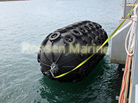
Floating Yokohama Pneumatic Rubber Fenders
Quick Answer: What Is a Floating Yokohama Pneumatic Rubber Fender?
A floating Yokohama pneumatic rubber fender is an air-filled, cylindrical marine fender made from synthetic-tire-cord-reinforced rubber layers. It floats at the waterline and absorbs berthing impact energy by compressing the trapped air inside its body. Also called a Yokohama fender, a floating pneumatic fender, or simply a pneumatic fender, it is the global standard for ship-to-ship (STS) transfer and tidal ship-to-dock operations.
The original Yokohama Pneumatic Rubber Fender was developed in 1958 by The Yokohama Rubber Co., drawing on the company’s technology for automobile tyres and rubber aircraft fuel tanks. Today, more than 60,000 units have been supplied worldwide for both ship-to-ship and ship-to-dock use. Its defining advantage is simple: instead of pushing back with rubber stiffness like a solid fender, it pushes back with gas compressibility — delivering high energy absorption with a low, non-spiking reaction force.
Note the terminology: Yokohama fender is the original brand name and is now used generically — much like Kleenex for tissues. Technically, every Yokohama fender is a pneumatic rubber fender, but not every pneumatic rubber fender is a Yokohama-brand product. In a purchase specification, always require ISO 17357-1:2014 compliance rather than relying on the words “Yokohama type” alone.
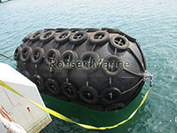
Floating Pneumatic Rubber Fenders
What Is a Floating Yokohama Pneumatic Rubber Fender? (Definition and Core Concept)
The Formal Definition
A floating Yokohama pneumatic rubber fender is a seam-free cylindrical buffer, constructed from multiple layers of rubber reinforced with synthetic tyre cord fabric, with compressed air sealed inside. It rests on the water surface, tracks tide and swell, and acts as a shock absorber between:
- Ship and ship — ship-to-ship (STS) transfer
- Ship and quay, jetty, or dolphin — ship-to-dock (STD) berthing
- Vessel and offshore structure — FPSO, SPM, FSO, FLNG, and offshore wind farm SOVs
Its defining feature is internal compressed air. Where a solid rubber fender relies on the material’s natural stiffness, a pneumatic fender uses air compression as the primary energy-absorbing mechanism. This gives it a “soft entry” force-deflection curve: the hull feels a progressive cushion rather than a hard wall.
Why “Floating” and “Yokohama” Matter in the Name
The word “floating” is not decorative — it is the structural differentiator from fixed fender systems. A compressed-air core gives the fender self-buoyancy, so it rises and falls with draft and tide, tracks vessel roll and pitch, and needs no adjustable brackets. A fixed cone or cell fender, by contrast, is bolted to the quay face and cannot move with water level.
The word “Yokohama” is the tradename of the original. In 1958 The Yokohama Rubber Co. applied tyre and rubber fuel-tank technology to create the world’s first air-filled marine fender. The design worked so well that the brand name became near-generic in ports worldwide. Modern qualified manufacturers produce “Yokohama-type” fenders that meet the same ISO 17357 performance benchmarks, and the original manufacturer itself has continued to develop the line — including the world’s largest floating fender for an LNG-FPSO, measuring 6.0 m × 11.5 m at P70, introduced in 2018.
Pneumatic Fender vs Foam-Filled Fender vs Solid Fender
These three categories are often confused because all three float and all three protect hulls. The table shows where each belongs:
| Feature | Pneumatic (Yokohama) | Foam-Filled | Solid (cone / cell / arch) |
| Energy mechanism | Compressed air + elastic cord strain | Closed-cell foam compression | Rubber material stiffness |
| Reaction force | Low and progressive | Medium | High (stiff) |
| Floats / tracks tide | Yes | Yes | No — fixed to quay |
| Can be deflated | Yes — for shipping and repair | No | No |
| Pressure tuning | Yes — P50 / P80 (and P70 at the large end) | No | No |
| Best use | STS, tidal berths, LNG / cruise / naval | Where deflation is impractical | Permanent high-traffic docks |
| Can mark hull | Sling type is non-marking; net type can mark | Low marking risk | Low marking risk |
Pneumatic fenders win for STS transfer, tidal berths, and any operation where low hull pressure matters — LNG carriers, aluminium hulls, cruise ships, and naval vessels. They can be deflated, packed, shipped in a container, and reinflated on site, which is a major advantage for salvage contractors and project work.
How Does a Yokohama Pneumatic Rubber Fender Work?
A pneumatic fender works by converting a vessel’s kinetic energy into uniform air compression plus elastic strain in the cord layers, then releasing that energy as the fender rebounds. Here is the complete impact cycle.
The Five Stages of Impact
- Approach — The fender floats at the hull contact point, tethered by slings or a chain-tire-net. It is already positioned at the waterline where contact will occur.
- Compression — The hull presses the reinforced rubber body, typically up to 60% deflection, which is the ISO test point.
- Uniform pressure rise — Internal air pressure rises evenly across the whole fender. There is no local buckling, so energy spreads across the entire body rather than concentrating at one spot.
- Energy conversion — Kinetic energy becomes compressed-air pressure plus elastic strain in the nylon / polyester cord layers. Roughly up to about 70% of the impact energy is absorbed.
- Rebound — When the vessel backs off, the air re-expands, the fender recovers its shape, and it is ready for the next impact. Fatigue-related performance deterioration is absent because the system uses the compressive elasticity of air.
Why the Reaction Force Stays Low
In a solid fender, the harder you push, the harder the material pushes back — the force-deflection curve rises steeply. In a pneumatic fender, gas compressibility means the reaction force rises progressively. The reaction force does not increase sharply even under excess load conditions, which is one of the ten principal advantages claimed by the original manufacturer. That is why pneumatic fenders are specified for sensitive hulls: the hull pressure stays within classification-society limits.
This soft, progressive response is also why the fender performs well at an angle. Under the angular compression test defined in ISO 17357-1:2014, the cylindrical flexible body continues to distribute load evenly along the hull at approach angles up to 15°. Energy absorption does not decrease significantly at inclined compression up to 15 degrees — a real advantage when ships rarely berth perfectly head-on.
Construction: The Three Layers and End Fittings
A pneumatic fender is built from the outside in as a multi-layer cylinder. The outer rubber, cord-reinforcement layers, and inner rubber are all vulcanized together under high pressure and cured at high temperature, ensuring superior bonding between layers of dissimilar characteristics.
The Three Structural Layers (ISO 17357-1:2014)
| Layer | Material / Function |
| Outer rubber layer | An NR / SBR blend abrasion-resistant skin. Protects the cord layers and inner rubber from seawater, UV, ozone, and repeated mechanical wear against hulls and quay faces. Standard colour is black; grey and other colours are available (for example naval use), though material-property requirements differ for non-black outer rubber. |
| Cord reinforcement | Cross-plied synthetic tyre cord — the burst-proof skeleton. The cord is arranged at an optimum angle so internal pressure is held and stress is distributed evenly; this is also what lets the fender remain shape-conformant under compression. Each layer is rubber-coated on both sides, isolating individual cords and reducing friction and wear as the body bends, compresses, and stretches. |
| Inner rubber layer (air-tight liner) | The seal. Its primary function is to retain the pressurised air inside the body at rated working pressure — typically 50 kPa or 80 kPa. This is what allows the fender to deliver consistent guaranteed energy absorption and reaction force. Loss of integrity in this layer reduces performance, making pressure monitoring a safety requirement rather than an optional maintenance task. |
ISO 17357-1:2014 Rubber Property Requirements (Minimum)
| Test item | Outer rubber | Inner rubber |
| Tensile strength (ISO 37), before aging | 18 MPa or more | 10 MPa or more |
| Elongation (ISO 37), before aging | 400% or more | 400% or more |
| Hardness (ISO 7619-1) | 60 ±10 (Type A) | 50 ±10 (Type A) |
| Tensile strength after aging | Not less than 80% of original | Not less than 80% of original |
| Elongation after aging | Not less than 80% of original | Not less than 80% of original |
| Tear resistance (ISO 34-1) | 400 N/cm or more | No requirement |
| Compression set (ISO 815-1) | 30% or less | No requirement |
| Static ozone aging (ISO 1431-1) | No cracks | No requirement |
Aging condition is air-oven aging at 70°C ±1°C for 96 h. These are minimum requirements of the standard; actual production values vary by manufacturer. Independent manufacturers publish inner-rubber air-tightness of up to six times the industry standard.
End Flanges, Valves, and Safety Equipment
At one or both ends, a steel bead ring secures the cord layers and a steel flange carries the valves and lifting points. Fenders of 2,500 mm diameter and above are fitted with a safety relief valve that releases air if pressure rises above the design limit — this is mandatory for that size class under the standard.
- Inlet and relief valves — inflation, pressure control, and automatic over-pressure release
- Lifting eyes and towing lugs — for handling and deployment
- Metal accessories — shackles, towing rings, swivels, and chain nets, typically hot-dip galvanised or stainless steel for seawater corrosion resistance
Cord angle and flange design are pressure-class-specific. This is the reason behind a critical safety rule: never inflate a P50 body to P80 pressure. The cord angle, end-ring geometry, and safety factors differ between classes.
Types of Pneumatic Rubber Fenders
ISO 17357-1:2014 classifies pneumatic fenders by construction into two production types, plus a specialised subclass. Choosing between them is a balance of abrasion protection, marking risk, weight, and deployment speed.
Type I — Chain-Tire-Net (CTN / Net Type)
A chain-tire-net or wire / fibre net wraps the body — chains with used tyres (often aircraft or truck tyres), frequently fitted with rubber sleeves to protect both the fender body and the vessel hull. The chains are galvanised for corrosion resistance, and hammerlocks fasten each intersection, connecting the net to the towing lug with shackles.
- Best suited to: heavy STS, tankers, LNG, and permanent berths
- Pros: highest abrasion resistance; long service life; load distributed over the body; performs in rough weather and against abrasive quay faces
- Cons: heavy; can mark sensitive hulls; slower to deploy
A Type I Single variant adds shoulder tyres for extra protection. CTN remains the default for high-frequency ports and oil and LNG terminals.
Type II — Sling Type
No chain-tire net. Instead, thick outer rubber is paired with integral slings or lifting eyes. It is manufactured in a purpose-built mould across the full size range.
- Best suited to: yachts, naval vessels, cruise ships, temporary berthing, and quick deployment
- Pros: lightweight; non-marking options; easy to handle and install
- Cons: less abrasion protection; requires careful operation near sharp edges
This is the clean-hull choice. Non-marking grey sling fenders are commonly specified for naval and prestige-vessel work.
Hydro-Pneumatic (Subclass)
Part air, part water ballast — typically about 60–70% water — used for submerged, low-freeboard contact. Applications include submarines and special low-hull-pressure operations where a fully floating fender would ride too high on the hull.
Derived Types
Manufacturers also offer variations built on the same pneumatic principle. Ribbed fenders replace chains and tyres with prominent ribbed stripes to reduce weight. Naval grey fenders are finished in non-marking grey for warships. Arch-type solid fenders and cell- and cone-type solid fenders occupy a separate category and are not pneumatic — they are worth knowing about when specifying a permanent high-traffic dock, but they do not float with the tide.
P50 vs P80: Same Size, Different Performance
Pneumatic fenders are supplied at two initial pressures, measured at 20°C. This is a design and order-stage decision — you do not tune it on site.
| Parameter | P50 — 50 kPa | P80 — 80 kPa |
| Energy absorption | Baseline (GEA) | Roughly 1.3–1.5× P50, i.e. ~35–40% more |
| Reaction force | Lowest | Proportionally higher |
| Typical use | LNG, aluminium hulls, yachts, naval, mid-size STS | VLCC / LNG high-energy berthing, high approach speed, limited fender count |
Selection rule: sensitive hull → P50. Heavy tanker STS with high approach velocity → P80. Then verify the hull can actually accept the higher hull pressure. The same nominal diameter × length can have very different performance depending on its pressure rating — specifying by dimensional size alone is a common and expensive mistake.
Reference Performance at 60% Deflection
GEA = Guaranteed Energy Absorption; R = Reaction Force. Tolerance is typically ±10%. Real values come from the manufacturer’s performance curves; the figures below are the standard reference set widely published for specification work.
| Size (Ø × L, mm) | P50 GEA (kJ) | P50 Reaction (kN) | P80 GEA (kJ) | P80 Reaction (kN) |
| 1000 × 1500 | 32 | 182 | 45 | 239 |
| 1500 × 3000 | 153 | 579 | 214 | 761 |
| 2000 × 3500 | 308 | 875 | 430 | 1150 |
| 2500 × 5500 | 943 | 2019 | 1317 | 2653 |
| 3300 × 6500 | 1814 | 3015 | 2532 | 3961 |
| 4500 × 12000 | 6473 | 7984 | 9037 | 10490 |
A Ø3.3 m × L6.5 m P80 fender absorbs roughly 2,532 kJ at 60% deflection — enough for VLCC-to-VLCC side-by-side transfer. The largest units in the range reach Ø4,500 × L12,000 mm, while the LNG-FPSO application mentioned above pushes the concept to 6.0 m × 11.5 m at P70.
ISO 17357-1:2014: The Standard That Defines Performance
ISO 17357 is the global benchmark for high-pressure floating fenders. It exists in two parts: ISO 17357-1:2014 for high-pressure pneumatic fenders and ISO 17357-2:2014 for low-pressure floating pneumatic rubber fenders. The original Yokohama design became the model for this standard in 2014, and all reputable manufacturers now build to it.
What ISO 17357-1 Actually Specifies
- Rubber physical properties — the outer and inner rubber requirements shown in the table above
- Cord-layer strength and construction
- Air-tightness of the inner liner
- Energy absorption and reaction force at 60% deflection
- Pressure ratings: 50 kPa and 80 kPa, measured at 20°C
- Safety-valve and end-flange requirements
- Type testing and production testing, plus marking and tolerances
Writing a Proper Purchase Specification
Do not accept “Yokohama type” as a full specification. A complete purchase line should read:
Pneumatic rubber fender, ISO 17357-1:2014, [P50 / P80], [Diameter × Length], [Type I net type / Type II sling type], with safety valve, mill certificate, third-party class approval (ABS / BV / DNV / CCS / LR).
Always request third-party certificates. Independent verification matters because performance claims are easy to state and hard to check without the test report.
How to Select the Right Yokohama Pneumatic Rubber Fender
Choosing the wrong fender leads to hull damage, berth structural failure, premature wear, and costly downtime. The right fender absorbs berthing energy safely, keeps reaction force within hull and quay limits, and performs reliably in tides, currents, and STS operations. Follow this sequence rather than guessing from DWT.
Step 1: Calculate Berthing Energy
Use the PIANC methodology. Do not select by vessel tonnes alone — this is the most common sizing error in the industry.
E = ½ × Me × V² × Ce × Cm × Cs × Cc
| Symbol | Meaning |
| Me | Effective displacement — vessel mass plus added mass of water |
| V | Approach velocity — typically 0.10–0.30 m/s for large vessels under tug assist |
| Ce | Eccentricity coefficient |
| Cm | Added-mass coefficient |
| Cs | Softness coefficient |
| Cc | Configuration / berth coefficient |
Step 2: Define the Constraints
- Allowable hull pressure — check classification-society rules
- Berth-structure reaction-force limit
- Tidal range and dolphin height
- Environmental exposure — waves, currents, temperature
Then select a fender where absorbed energy ≤ GEA at 60% deflection, with reaction force ≤ hull and structure limits. Apply a typical safety factor of 1.1–1.25 to the design berthing energy.
Step 3: Match to the Performance Curve
Compare your calculated energy against the GEA values in the standard size table, not against dimensional size. The Ø3300 × 6500 mm example shows why: P50 delivers approximately 1,814 kJ at 3,015 kN, while P80 delivers approximately 2,532 kJ at 3,961 kN. Same dimensions, very different performance.
Step 4: Choose P50 or P80
- P50 — 50 kPa: use for yachts, naval vessels, aluminium hulls, LNG carriers, cruise ships, and any sensitive coating or structure
- P80 — 80 kPa: use for VLCCs, large tankers, high approach velocity, STS transfer, and operations where fender count is limited
And again, as a safety matter: never inflate a P50-rated fender to 80 kPa.
Step 5: Choose Net Type or Sling Type
| If your priority is… | Choose |
| Permanent berth, high-frequency port, STS oil / LNG, rough weather, abrasive quay | Type I — Chain-tire-net, P80 |
| Yacht, naval, cruise hull, temporary berthing, fast deployment | Type II — Sling type, P50 |
| Submerged, low-freeboard contact | Hydro-pneumatic |
Installation, Inflation, and Maintenance Best Practices
A pneumatic fender is low-maintenance, not no-maintenance. The items below are the difference between a 6-year service life and a 15-year one.
Pre-Deployment Checklist
- Inflate with clean, dry air or nitrogen to the rated initial pressure — never use moist or contaminated air
- Verify the safety relief valve functions correctly before deployment
- Inspect the chain / tire net or sling for corrosion, wear, or loose connections
- Confirm end-flange bolts and shackles are tightened to specification
- Tether the fender so it stays in the intended contact zone through the full tidal range
Routine Maintenance
- Pressure checks — monthly or before each operation. Temperature changes affect pressure; hot sun can raise pressure by 10–15%
- Visual inspection — cuts more than 1 cm deep, exposed cord fabric, valve leakage, tire-net wear
- Cleaning — rinse with fresh water after heavy fouling to remove salt and silt
- Valve service — replace valve cores every 6 months in high-use environments
Steel wire should be run through a rubber hose wherever it contacts the fender body, to prevent puncturing the rubber. The area around the fender must be kept free of hard, sharp objects. When tying wire to the fender, protect the body from the metal fittings.
Storage When Not in Use
- Deflate partially or fully
- Store in a cool, dry, well-ventilated area away from direct sunlight and ozone sources (electric motors, welding equipment)
- Keep away from sharp objects and chemicals
With proper care, a high-quality pneumatic fender typically lasts 10–15 years. Net-type fenders in moderate service can exceed 10 years; independent guidance places the general range at 6–10 years, with quality units lasting longer when pressure is kept within ±5% of rated.
Replace Immediately If…
- Cuts expose cord fabric
- Air leakage cannot be stopped by valve service
- Permanent deformation exceeds the manufacturer’s tolerance
- The safety relief valve no longer operates
Applications of Floating Yokohama Pneumatic Rubber Fenders
The range of use has expanded continuously since 1958, tracking the growth of progressively larger oil tankers — VLCCs, ULCCs, Q-Max size gas carriers, bulk carriers — and floating structures including FPSO, FLNG, and FRSU. Common applications include:
- Ship-to-ship oil and LNG transfer
- Ship-to-dock berthing
- Oil terminals and VLCC / ULCC berths
- FPSO and FSU offloading
- Offshore wind and supply-vessel operations
- Cruise terminals
- Naval and submarine berthing
- Floating docks and marinas
- Emergency mooring and lay-by protection
Floating fenders are particularly valuable at tidal terminals. One documented case involved a tidal harbour in Southeast Asia that replaced fixed rubber fenders on a marginal berth with sling-type Yokohama fenders; the berthing window expanded because the fenders stayed in the hull contact zone through the full tidal range without manual repositioning.
Frequently Asked Questions About Floating Yokohama Pneumatic Rubber Fenders
Are floating pneumatic rubber fenders the same as Yokohama fenders?
Yes — in practice the terms are used interchangeably. “Yokohama fender” is the industry tradename, named after The Yokohama Rubber Co., which pioneered the design in 1958. Technically, a Yokohama fender is a floating pneumatic rubber fender. The original brand is one manufacturer; ISO-style “Yokohama-type” fenders are produced by other qualified manufacturers to the same benchmark.
Are pneumatic rubber fenders ISO certified?
Reputable manufacturers produce to ISO 17357-1:2014 (high-pressure) or ISO 17357-2 (low-pressure). Always request third-party certification from a classification society — ABS, BV, DNV, CCS, or LR — rather than accepting a claim of compliance without documentation.
What pressure should a pneumatic rubber fender be inflated to?
Usually 50 kPa (P50) or 80 kPa (P80) at 20°C. The rating is fixed at the design and order stage; never inflate a P50 body to P80 pressure. Large units can carry a relief-valve setting appropriate to their design pressure — the LNG-FPSO example mentioned earlier operates at P70.
Can pneumatic fenders be used on a fixed dock instead of cone fenders?
They can, but usually should not if the berth is permanent and high-traffic. Pneumatics cost more to maintain — air checks, net wear — and can drift if not properly tensioned. Fixed docks generally do better with Super Cone or cell fenders, reserving pneumatics for STS work or extreme tidal cases where flotation matters.
What is the difference between a pneumatic fender and a foam fender?
A pneumatic fender uses compressed air and can be deflated for shipping and repair. A foam fender uses closed-cell foam; it floats but cannot be pressure-tuned. Pneumatics offer pressure-selectable performance and containerised transport; foam fenders are the choice where deflation is impractical.
What is the difference between a pneumatic fender and a marine airbag?
They are related but serve different jobs. A pneumatic rubber fender protects a vessel and structure during berthing or STS contact. A marine airbag is used for launching, lifting, and moving vessels or heavy objects — it is not a fender and must not be substituted for one in a berthing specification.
How long does a pneumatic rubber fender last?
Typically 6–15 years with proper maintenance, depending on duty cycle, exposure, and whether the net or sling type is used. Net-type fenders in moderate service commonly exceed 10 years; service life is governed primarily by pressure control, net corrosion, and abrasion, not by calendar age.
What is GEA and why does it matter?
GEA stands for Guaranteed Energy Absorption. It is the integral of reaction force over deflection to 60%, measured at a compression rate of no more than 80 mm/min under the ISO parallel-compression test. It is the single number that must exceed your calculated berthing energy — and it is always read at 60% deflection with a tolerance of typically ±10%.
Key Takeaways
- A floating Yokohama pneumatic rubber fender is an air-filled, cord-reinforced rubber cylinder that absorbs berthing energy through air compression.
- It was developed by The Yokohama Rubber Co. in 1958 and has become the generic industry benchmark, with more than 60,000 units supplied worldwide.
- “Yokohama type” is not a specification — always specify ISO 17357-1:2014 plus pressure class, size, type, safety valve, and class approval.
- P50 gives lower reaction force for sensitive hulls; P80 adds roughly 35–40% more energy absorption for heavy STS and high approach speeds.
- Net type protects against abrasion; sling type protects against hull marking. Choose by duty, not by price.
- Size by berthing energy using the PIANC formula — never by DWT or dimensional size alone.
- Maintain it: monthly pressure checks, fresh-water rinsing, and immediate replacement when cord fabric is exposed or leakage cannot be stopped.
Whether you are a port buyer specifying a fleet for a new terminal, a marine engineer checking a berthing calculation, or an operator running an STS transfer, understanding these fenders means choosing a system that protects both the vessel and the structure — and keeps the reaction force exactly where it should be.

