

What Is Support Buoy and Pick Up Buoy?
▍Quick answer: what is a support buoy and pick up buoy?
| Direct answer — optimised for the featured snippet (≈ 48 words) |
| A support buoy is a heavy-duty, foam-filled float with a steel central member that carries the weight of a chafe chain in an SPM or CALM system. A pick-up buoy is a smaller marker float on the end of a pick-up (messenger) rope, used to retrieve that chain end. They sit next to each other on the same end of the hawser, but they are not the same product. |
▍What is a support buoy and pick up buoy in offshore operations?
- Support buoy — a load-carrying float
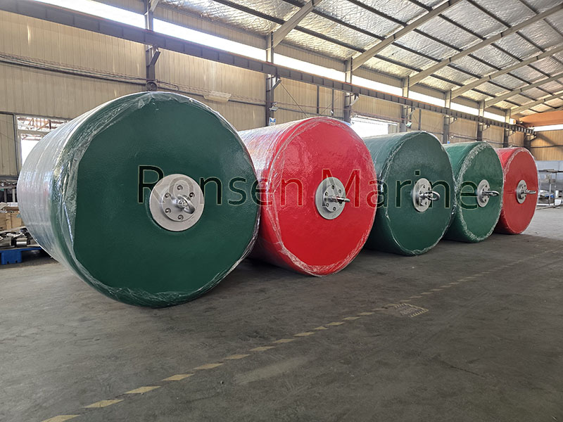
Support Buoys
A support buoy (also called a chain support buoy or flotation device) is a heavy-duty offshore float, normally foam-filled with a closed-cell PE or EVA core, a steel central strength member and a polyurethane skin. Its job is to support the submerged weight of the chafe chain and keep the catenary of the mooring hawser in the correct shape while the berth is unoccupied.
Per the OCIMF Recommendations for Equipment Employed in the Bow Mooring of Conventional Tankers at Single Point Moorings, 4th edition: “When the berth is unoccupied, each chafe chain may be supported by flotation devices.” The same guidance states that reserve buoyancy must be at least 20% of the weight in air of the material being supported — a figure that appears unchanged from the 3rd edition (1993) through the current 1st edition (2018).
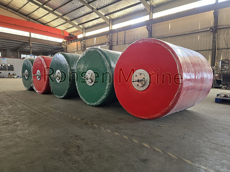
Pick Up Buoys
Two connection methods are used:
- Swivel-ended type: Swivel-ended type: connected by a short length of chain to the end link of the chafe chain, adjacent to the hawser. A swivel at each end prevents twist accumulation.
- Chain-through type: Chain-through (locking plate) type: the chafe chain passes through a central steel tube in the buoy body and is locked in place by a chain-locking plate and single locking pin.
- Pick-up buoy — a marker, not a lifting device
In this context “pick up buoy” means the small marker float on the end of the pick-up arrangement. The arrangement consists of:
- a pick-up (messenger) rope, typically 150 m of floating rope, usually polypropylene-based;
- an eye at each end, one shackled to the ship end of the chafe chain;
- a small pick-up or marker buoy that keeps the rope end visible at the surface.
OCIMF gives the working range as 120–180 m in length and 64–80 mm in diameter. At some terminals the pick-up rope is disconnected when the berth is empty, in which case a separate recovery arrangement is needed to reconnect it.
The pick-up rope is a floating messenger, not a load path. It is sized to be handled by a boat hook from a supply vessel — not to carry hawser tension. That distinction prevents the single most common site error: treating the pick-up rope as a mooring component and leaving it in the stopper under load.
▍How a support buoy and pick-up buoy work together
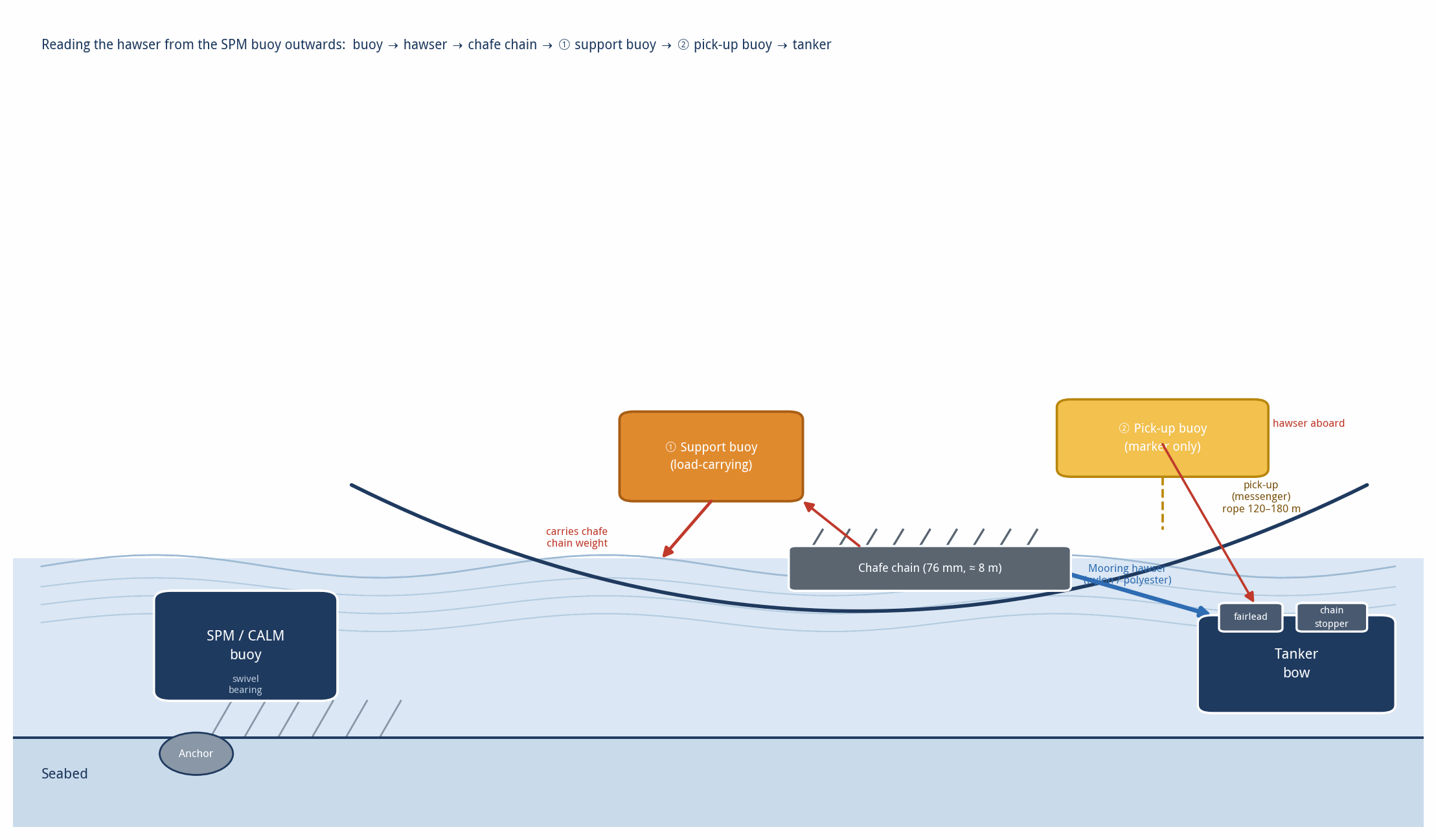
Reading the hawser from the SPM buoy outwards, the sequence is fixed by OCIMF:
- Buoy-side shackle and bridle assembly, connected to the pad eye on the buoy deck.
- Mooring hawser shackle.
- Mooring hawser (nylon or polyester, single-leg or grommet-leg type).
- Chafe chain assembly — OCIMF Type A or B, grade R3 or R4, attached to protect the synthetic rope from the tanker fairlead.
- Support buoy — carries the chafe chain when no tanker is present.
- Pick-up messenger lines and marker (pick-up) buoy for retrieval from the water.
- Oblong plate on the chafe chain end, for connecting to the pick-up rope bow shackle.
When a VLCC or Suezmax approaches, a supply vessel hooks the marker buoy, follows the messenger rope to the chafe chain end, and hands it to the tanker deck. The tanker hauls the hawser in, places the chafe chain in the chain stopper, and the support buoy is left floating alongside or tied back. Reversing the sequence at departure returns the chain to the support buoy.
Figure 1 — Bow-mooring hawser sequence showing both buoys on the same end of the hawser
 ▍Support buoy vs pick-up buoy: the comparison that decides the purchase
This is the table buyers and engineers actually need. Every row is a decision point.
| Feature | Support buoy | Pick-up buoy (marker) |
| Primary job | Carry the submerged weight of the chafe chain and shape the hawser catenary | Mark the chain end and let crew retrieve it |
| Position on the hawser | On the chafe chain, adjacent to the hawser | At the shipboard end of the pick-up rope |
| Load path | Axial chain tension through steel tube, gussets and load flanges | Pick-up rope tension only — never the hawser load |
| Reserve buoyancy rule | ≥ 20% of the weight in air of the supported material (OCIMF) | Enough to keep the rope end at the surface |
| Net buoyancy range (example product line) | 900 kg to 5,000 kg typical; custom to project | 90 kg to 2,750 kg |
| Safe working load | Project-specific; certified by the steelwork, not the foam | Light-duty; confirm before any lifting use |
| Connection | Central tube (64/76/84 mm chain) or short pendant with swivel | Shackle eye on the pick-up rope end |
| Main failure mode | Steelwork fatigue, PU skin abrasion, loss of freeboard | Rope chafe at the eye, buoyancy loss, faded visibility |
| Replacement driver | Annual thickness and freeboard check | Rope condition and colour loss at each berthing |
| The one-sentence answer for any tender or inspection form |
| Support buoy = load-bearing float that carries the chafe chain. Pick-up buoy = small marker float that shows crew where the chain end is. Same neighbourhood on the hawser, different functions, different specifications. |
▍How to size a support buoy: the calculation buyers get wrong
The calculation is simple, but two mistakes appear repeatedly in tender documents.
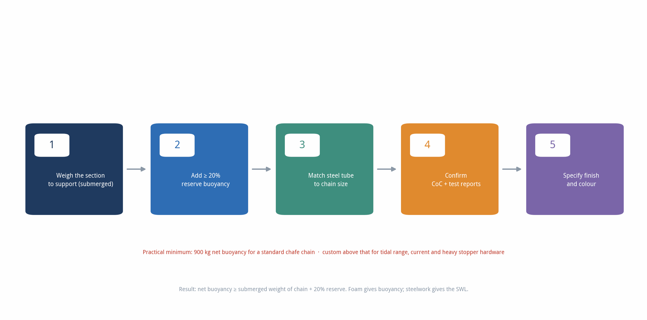
Step 1 — establish the submerged weight
Weigh the section to be supported: the chafe chain (typically about 8 m of 76 mm stud-link chain, sometimes longer when a chain-through buoy is used), plus any chain stopper hardware, shackles and the short pendant. Use the submerged weight, not the weight in air.
Step 2 — apply the 20% reserve rule
Net buoyancy must equal the submerged weight plus at least 20% reserve. A 900 kg net buoyancy buoy is therefore the practical minimum for a standard chafe chain. Projects operating in tidal ranges, strong currents or with a heavy chain stopper assembly should increase this margin rather than rely on the minimum.
Step 3 — match the steelwork to the chain size
The foam provides buoyancy; the steelwork carries the load. Specify central tube diameter for 64 mm, 76 mm and 84 mm chain, and confirm the chain-locking plate arrangement. Foam grade alone does not determine the safe working load.
Step 4 — confirm compliance documentation
Request a Certificate of Conformity and material test reports for the polyurethane skin and foam core. OCIMF references: Guidelines for the Purchasing and Testing of SPM Hawsers (2000) for wet break strength and fatigue performance, and the 4th edition Recommendations for Equipment Employed in the Bow Mooring of Conventional Tankers at Single Point Moorings for the buoyancy and chafe chain rules.
Step 5 — environment and finish
Factor tidal range, current velocity and wave height into the freeboard calculation. For the steelwork, choose hot-dip galvanised or epoxy-coated. For the skin, specify nylon-reinforced polyurethane and a colour that remains visible after two years at sea — yellow, orange and red are standard, with grey used where staining of white hulls is a concern.
| Three mistakes to avoid: (1) assuming “foam-filled” means unsinkable without checking the skin thickness and abrasion rating; (2) using a pick-up buoy as a load-carrying support buoy because the catalogue lists a similar SWL; (3) forgetting that a chain-through arrangement increases the chafe chain length, so the original chain order no longer fits. |
Figure 2 — Support buoy sizing: the five-step calculation
▍Support buoy construction: why foam-filled beats air-filled
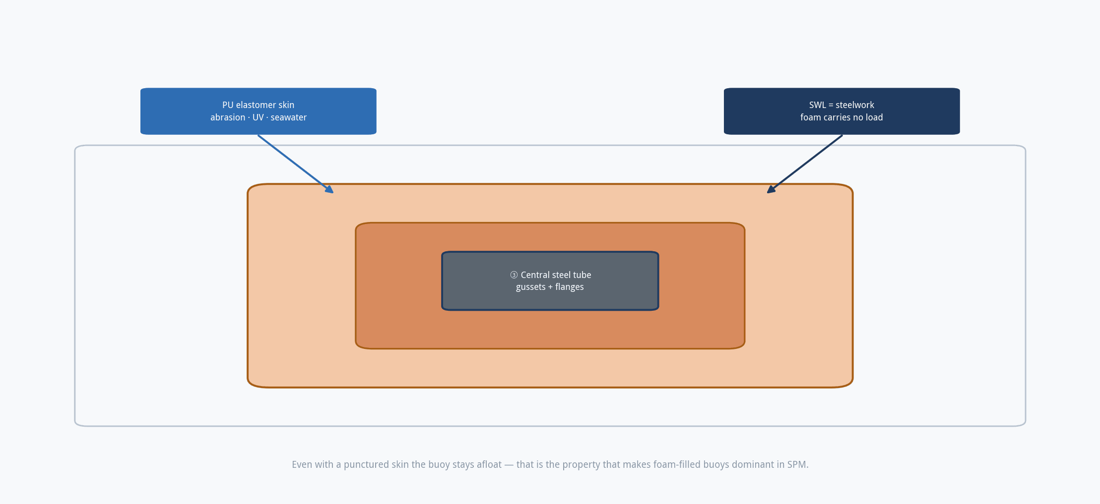
The three-layer closed-mould construction used by the major manufacturers is the reason these buoys last for decades rather than seasons.
| Layer | Material | Function |
| Core | Closed-cell PE or EVA foam | Watertight even if the skin is punctured; the buoy stays afloat |
| Reinforcement | High-tenacity nylon tyre cord / filament | Absorbs tensile stress from the chain, limits elongation under dynamic load |
| Outer skin | Polyurethane elastomer, nylon-reinforced | Abrasion, UV and seawater resistance; “self-fendering” under impact |
| Strength member | Central steel tube, gussets, load-distribution flanges | Carries the actual SWL — the foam does not |
Typical specification values (PE foam core / PU skin): foam density 40–45 kg/m³; tensile strength ≥ 289 kPa; 10% deflection compressive strength ≥ 27 kPa; PU hardness 75–95 Shore A; tensile strength ≥ 13.8 MPa; elongation ≥ 300%; Ross flex life ≥ 10,000 cycles; abrasion resistance ≥ 100 NBS.
Because the core is closed-cell, a punctured skin does not turn the buoy into a dead weight. That single property is why foam-filled buoys dominate mission-critical SPM applications.
Figure 3 — Three-layer closed-mould construction of a support buoy
▍Where support buoys and pick-up buoys are used
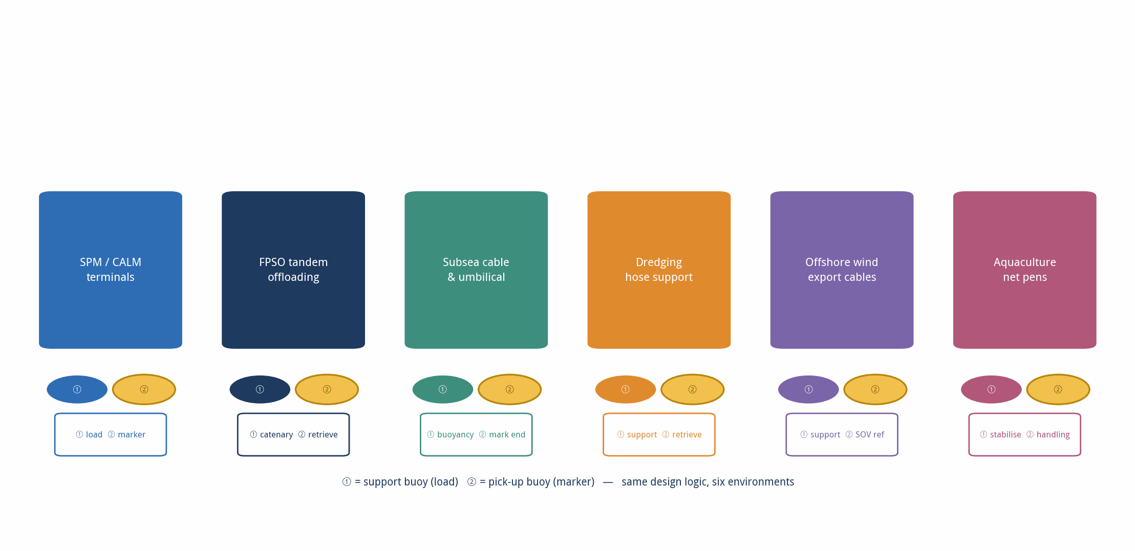
The original and still largest application is the bow mooring of conventional tankers at CALM and SALM terminals. From there the same design logic has spread into any operation where a heavy line must be kept off the seabed and recovered repeatedly.
| Application | Role of the support buoy | Role of the pick-up buoy |
| SPM / CALM terminals | Mid-line chafe chain support, reduced hawse-pipe tension | Recover the chain end for tanker connection |
| FPSO tandem offloading | Hawser catenary control behind the FPSO | Retrieve the hawser pendant in harsh sea states |
| Subsea cable and umbilical lay | Controlled buoyancy during lay operations | Mark and recover the messenger / ROV umbilical end |
| Dredging | Support discharge pipes and suction hoses | Temporary retrieval of hose ends |
| Offshore wind | Export cable support, marker pendants | SOV and diver retrieval reference |
| Aquaculture | Stabilise mooring lines and net pens | Auxiliary line handling |
Figure 4 — Six application environments, two components
▍Why this detail matters: the Girassol case
The value of getting buoyancy, chain support and hawse articulation right is best illustrated by what happens when they are wrong.
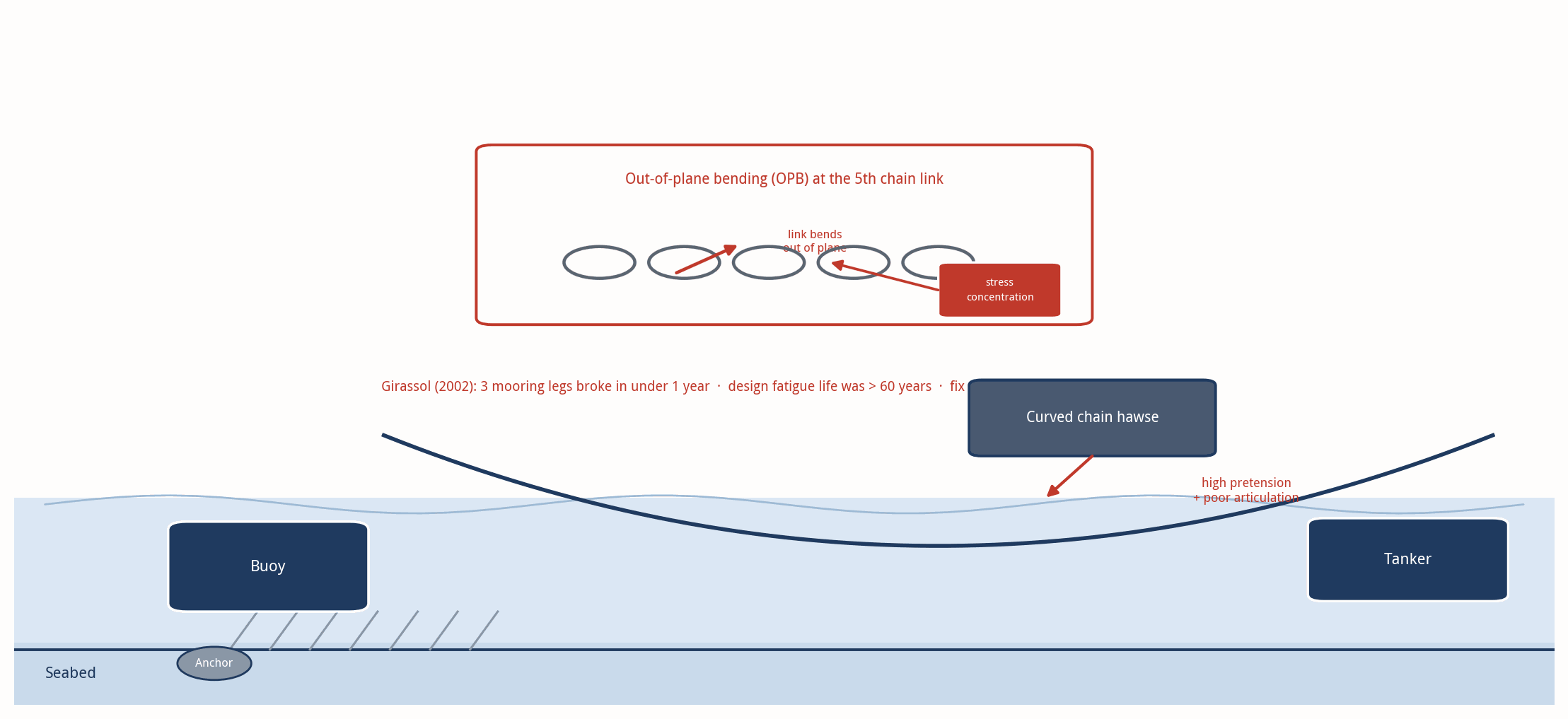
The Girassol loading buoy was installed in September 2001 in 1,350 m of water off Angola. It exported stabilised crude via two 16-inch mid-water export lines to tankers moored at the buoy, 1 nautical mile from the FPSO. In May 2002 — 235 days after installation — one group of three anchor legs broke almost simultaneously. A fourth leg ruptured a month later. The design had been carried out to API RP 2SK with a calculated fatigue life of more than 60 years.
The root cause was out-of-plane bending (OPB) fatigue at the fifth link of the upper chain segment inside the curved chain hawse. High pretension, poor articulation and friction-induced locking between adjacent links bent the first free link out of its plane, creating a severe stress concentration. Three mooring legs failed in under a year; the rope segment of a fifth leg failed by load transfer after an earlier accidental two-thirds cut.
The fix was a redesign of both the top chain segment size and the hawse connection, introducing a chain-connecting arm (CCA), plus a new method for estimating bending fatigue damage. Production continuity was maintained throughout by the in-place tandem offloading contingency.
The lesson for support buoy and pick-up buoy specification is direct: reserve buoyancy and hawse/fairlead articulation are not separate issues. A buoy that leaves too much weight on the chain, or a connection that does not articulate, moves fatigue damage into exactly the place Girassol exposed.
Figure 5 — OPB fatigue at the fifth chain link: the Girassol mechanism
▍Support buoy vs navigation buoy vs mooring buoy vs pick-up buoy
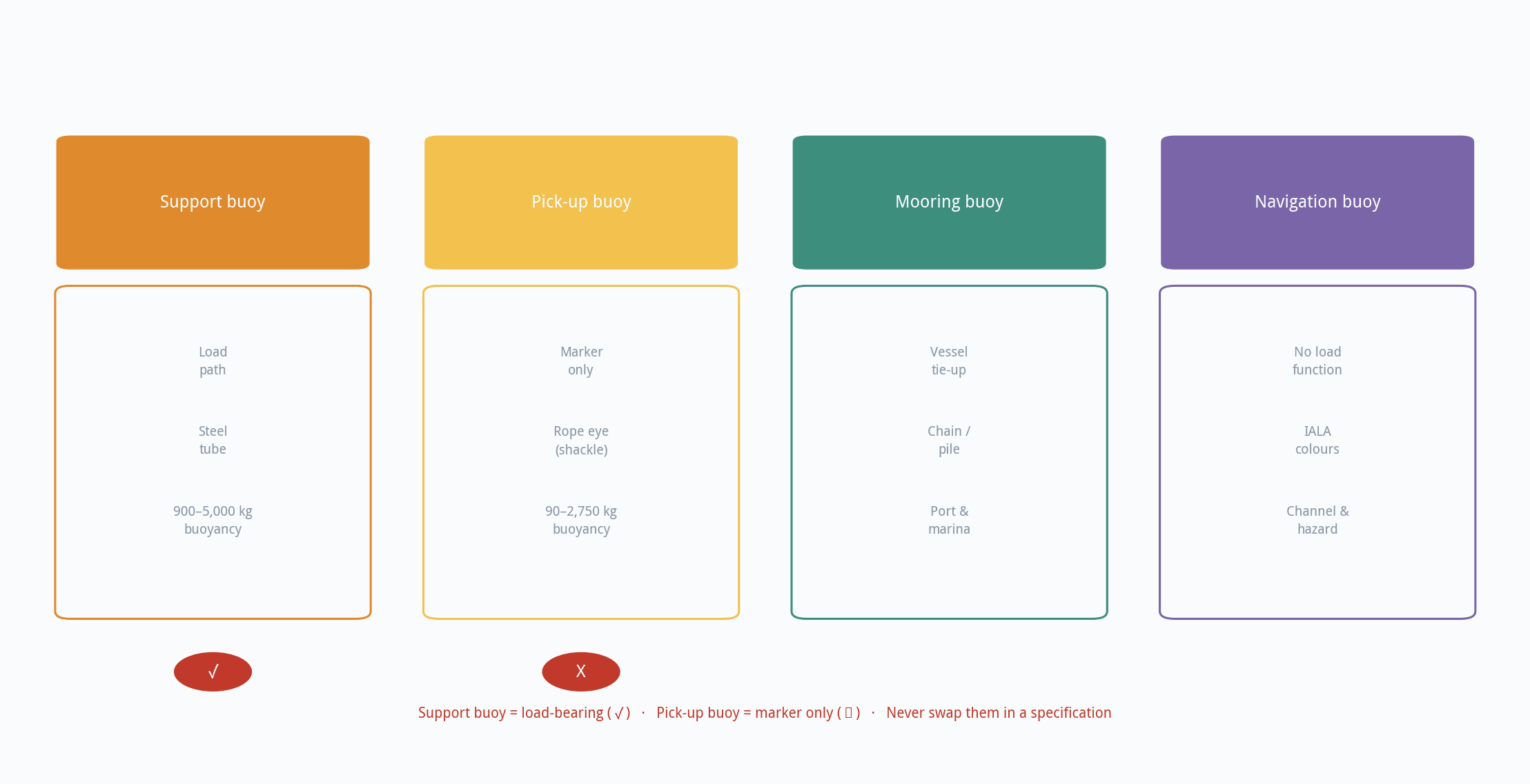
These four are routinely confused in tender specifications, and the error is expensive.
| Type | Main purpose | Typical user | Load-carrying? |
| Support buoy | Lifts and protects chains, hoses and cables | Terminal engineers, EPC contractors | Yes — primary function |
| Mooring buoy | Provides a tie-up point for a vessel | Ports, marinas, ship crews | Yes, but for the vessel |
| Navigation buoy | Marks channels, hazards and safe water | Mariners, port authorities | No |
| Pick-up buoy | Marks and retrieves a line or chain end | Offshore crews, workboats | No — retrieval aid only |
Figure 6 — Four buoy types compared
▍Inspection and maintenance: the 12-month cycle that prevents failure
The maintenance burden is deliberately low, which is why skipped inspections are so damaging — there is no warning before a buoyancy loss becomes a chain-on-seabed event.
- Annually: Check PU skin annually for deep cuts, abrasion and exposed foam. Repair before the next deployment.
- After each deployment: Rinse with fresh water after deployment in polluted or tropical waters.
- Every 12 months: Check galvanised steelwork for corrosion every 12 months; touch up coating before pitting starts.
- At each recertification: Confirm net buoyancy and freeboard against the original calculation, especially after a skin repair.
- In storage: Store spare buoys in shaded, ventilated areas. UV exposure is cumulative and accelerates chalking.
For the pick-up rope, inspect the eye splices and the shackle pin before every berthing. Polypropylene degrades slowly in sunlight and rapidly at chafe points — a rope that looks sound can fail at the eye.
▍FAQ: what readers ask after reading this
What is a support buoy and pick up buoy?
A support buoy is a heavy-duty float that supports the weight of a chafe chain in an SPM or CALM system. A pick-up buoy is the small marker float on the end of the pick-up rope, used to retrieve and haul the mooring hawser aboard a tanker.
Are support buoy and pick up buoy the same thing?
No. A support buoy carries load through a steel central member. A pick-up buoy marks and retrieves a line end and is not a load-bearing component. Suppliers sometimes list “pick-up buoy” as a product category, which adds to the confusion.
How much reserve buoyancy does a support buoy need?
At least 20% of the weight in air of the material being supported, per OCIMF. A 900 kg net buoyancy buoy is the practical minimum for a standard chafe chain.
What size is the chafe chain at the tanker end?
76 mm stud-link chain is the standard recommendation, forming a single chain about 8 m or more in length. A chain-through support buoy may require a longer chain. OCIMF Types A and B (grades R3/R4) cover the full range of ship sizes.
How long is a pick-up rope?
Typically 150 m of floating polypropylene-based rope, with an eye at each end; the working range is 120–180 m in length and 64–80 mm in diameter.
Are foam-filled support buoys really unsinkable?
In practical terms, yes. The closed-cell PE/EVA core does not absorb water even if the PU skin is punctured, so the buoy retains buoyancy. The steelwork and end fittings remain the limiting factor for load capacity.
Can I use a pick-up buoy to lift a chain?
Not unless the datasheet explicitly certifies it for that load with a stated SWL and a Certificate of Conformity. Most pick-up buoys are rated for messenger-line loads only.
What standards govern this equipment?
OCIMF Recommendations for Equipment Employed in the Bow Mooring of Conventional Tankers at Single Point Moorings (current 1st edition, 2018; 4th edition guidance on support buoys and chafe chains) and the Guidelines for the Purchasing and Testing of SPM Hawsers (2000).
- • •
▍Key takeaways
- Support buoy and pick up buoy describe two different components that sit next to each other on the same end of the hawser — not one product.
- The OCIMF rule is clear: reserve buoyancy must be at least 20% of the weight in air of the supported material.
- The foam provides buoyancy; the steelwork carries the load. Never infer SWL from buoyancy alone.
- A pick-up rope is a floating messenger, not a load path. Treat it as such in procedures and stopper policy.
- OPB fatigue at the hawse/chain connection is a real failure mode — size the top chain and articulate the connection before blaming the buoy.
For project use, the safest order of work is: calculate submerged weight first, add the 20% reserve, match the steelwork to the chain size, then confirm compliance documentation before release for manufacture.
